Mechanical Testing of Materials
Samples of engineering materials are subjected to a wide variety of mechanical tests to measure their strength or other properties of interest. Such samples, called specimens, are often broken or grossly deformed in testing. Some of the common forms of test specimen and loading situation are shown in Fig. 1. The most basic test is simply to break the sample by applying a tensile force, as in (a). Compression tests (b) are also common.
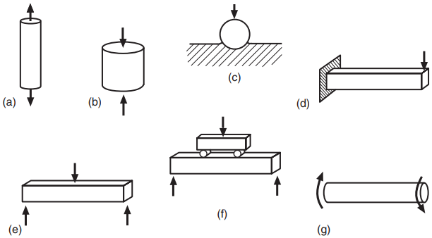
In engineering, hardness is usually defined in terms of resistance of the material to penetration by a hard ball or point, as in (c). Various forms of bending test are also often used, as is torsion of cylindrical rods or tubes. The simplest test specimens are smooth (unnotched) ones, as illustrated in Fig. 2(a).
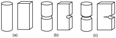
More complex geometries can be used to produce conditions resembling those in actual engineering components. Notches that have a definite radius at the end may be machined into test specimens, as in (b). (The term notch is used here in a generic manner to indicate any notch, hole, groove, slot, etc., that has the effect of a stress raiser.) Sharp notches that behave similar to cracks are also used, as well as actual cracks that are introduced into the specimen prior to testing, as in (c).
Mechanical Testing of Materials
To understand mechanical testing, it is first necessary to briefly consider materials testing equipment and standard test methods. We will then discuss tests involving tension, compression, indentation, notch impact, bending, and torsion. Various more specialized tests are discussed in later articles in connection with such topics as brittle fracture, fatigue, and creep.
Test Equipment
Equipment of a variety of types is used for applying forces to test specimens. Test equipment ranges from very simple devices to complex systems that are controlled by digital computer. Two common configurations of relatively simple devices called universal testing machines are shown in Fig. 3. These general types of testing machine first became widely used from 1900 to 1920, and they are still frequently employed today.
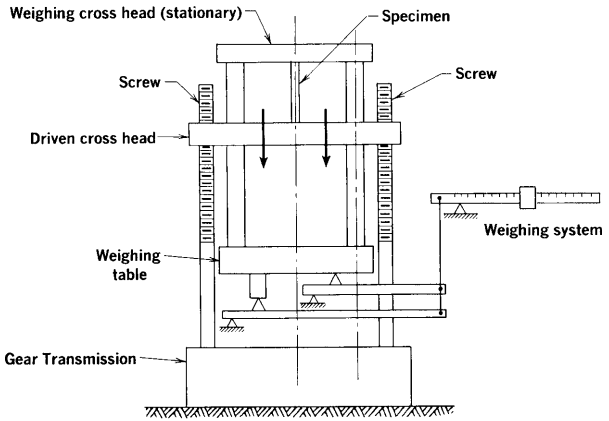
In the mechanical-screw-driven machine (top diagram), rotation of two large threaded posts (screws) moves a crosshead that applies a force to the specimen. A simple balance system is used to measure the magnitude of the force applied.
Forces may also be applied by using the pressure of oil pumped into a hydraulic piston (bottom diagram). In this case, the oil pressure provides a simple means of measuring the force applied. Testing machines of these types can be used for tension, compression, or bending, and torsion machines based on a similar level of technology are also available.
The introduction of the Instron Corp. testing machine in 1946 represented a major step, in that rather sophisticated electronics, based initially on vacuum tube technology, came into use. This is also a screw-driven machine with a moving crosshead, but the electronics, used both in controlling the machine and in measuring forces and displacements, makes the test system much more versatile than its predecessors.
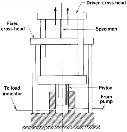
Around 1958, transistor technology and closed-loop automation concepts were employed by the forerunner of the present MTS Systems Corp. to develop a high-rate test system that used a doubleaction hydraulic piston, as illustrated in Fig. 4.
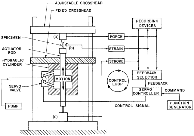
The result is called a closed-loop servohydraulic test system. Desired variations of force, strain, or testing machine motion (stroke) can be enforced upon a test specimen.
Note that the only active motion is that of the actuator rod and piston combination. Hence, the stroke of this actuator replaces the crosshead motion in the older types of testing machines.
The closed-loop servohydraulic concept is the basis of the most advanced test systems in use today. Integrated electronic circuitry has increased the sophistication of these systems. Also, digital computer control and monitoring of such test systems has steadily developed since its introduction around 1965.
Sensors for measuring forces and displacements by means of electrical signals are important features of testing machines. Linear variable differential transformers (LVDTs) were used in this manner relatively early for measuring displacements, which in turn give strains in test specimens.
Wire strain gages were developed in 1937, and the wire elements were replaced by thin foil elements, starting around 1952. Strain gages change their resistance when the material to which they are bonded is deformed, and this change can be converted to an electrical voltage that is proportional to the strain.
They can be used to construct load cells for measuring applied force and extensometers for measuring displacements on test specimens. The Instron and closed-loop servohydraulic testing machines require electrical signals from such sensors. Strain gages are the type of transducer primarily used at present, but LVDTs are also often employed.
Besides the general-purpose test equipment just described, various types of special-purpose test equipment are also available. Some of these will be discussed in later chapters as appropriate.
Standard Test Methods
The results of materials tests are used for a variety of purposes. One important use is to obtain values of materials properties, such as the strength in tension, for use in engineering design. Another use is quality control of material that is produced, such as plates of steel or batches of concrete, to be sure that they meet established requirements.
Such application of measured values of materials properties requires that everyone who makes these measurements does so in a consistent way. Otherwise, users and producers of materials will not agree as to standards of quality, and much confusion and inefficiency could occur. Perhaps even more important, the safety and reliability of engineered items requires that materials properties be well-defined quantities.
Therefore, materials producers and users and other involved parties, such as practicing engineers, governmental agencies, and research organizations, have worked together to develop standard test methods. This activity is often organized by professional societies, with the American Society for Testing and Materials (ASTM International) being the most active organization in this area in the United States.
Many of the major industrial nations have similar organizations, such as the British Standards Institution (BSI). The International Organization for Standardization (ISO) coordinates and publishes standards on a worldwide basis, and the European Union (EU) publishes European Standards that are generally consistent with those of ISO.
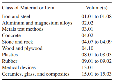
A wide variety of standard methods have been developed for various materials tests, including all of the basic types discussed in this chapter and other, more specialized, tests considered in later chapters. The Annual Book of ASTM Standards is published yearly and consists of more than 80 volumes, a number of which include standards for mechanical tests.
The details of the test methods differ, depending on the general class of material involved, such as metals, concrete, plastics, rubber, and glass. The ASTM standards are organized according to such classes of material, with Table 1 identifying the volumes that contain standards for mechanical testing.
Containing Basic Mechanical Test Methods
Volume 03.01 contains numerous test standards for metals, including a variety of basic mechanical tests. Other mechanical testing standards are included in the volumes for more specific classes of material, along with standards of other types. For each class of material, there are one or more standard methods for tests in tension, compression, and bending, and also often for hardness, impact, and torsion.
Volume 13.01 contains standards for materials and devices used in medicine, such as mechanical tests for bone cement, bone screws, fixation devices, and components of artificial joints. The various national organizations, the EU, and ISO have standards that parallel those of ASTM in many areas, with the details for a given test sometimes differing among these.
Test standards give the procedures to be followed in detail, but the theoretical basis of the test and background discussion are not generally given. Hence, one purpose of this book is to provide the basic understanding needed to apply materials test standards and to make intelligent use of the results.
Measured values of any property of a given material, such as its elastic modulus, yield strength, or hardness, are subject to statistical variation. This issue is often addressed in test standards. Note that multiple measurements of a given property are needed to obtain an average value and to characterize the statistical scatter about this average.
Tension Test
A tension test consists of slowly pulling a sample of material with an axial force until it breaks. The test specimen used may have either a circular or a rectangular cross section, and its ends are usually enlarged to provide extra area for gripping and to avoid having the sample break where it is being gripped. Specimens both before and after testing are shown for several metals and polymers in Figs. 1 and 2.
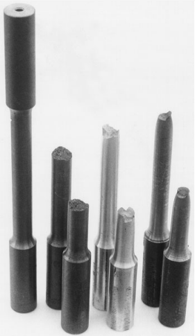
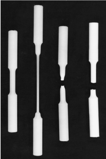
diameter test section, a partially tested specimen of high-density polyethylene (HDPE), and broken specimens of nylon 101 and Teflon (PTFE).
Methods of gripping the ends vary with specimen geometry. A typical arrangement for threaded-end specimens is shown in Fig. 3.
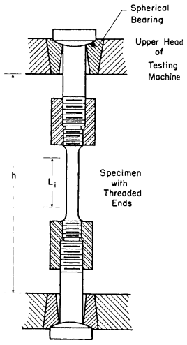
Note that spherical bearings are used at each end to provide a pure tensile force, with no undesirable bending. The usual manner of conducting the test is to deform the specimen at a constant speed. For example, in the universal testing machines the motion between the fixed and moving crossheads can be controlled at a constant speed. Hence, distance h in Fig. 3 is varied so that
dh/dt = h = constant
The axial force that must be applied to achieve this displacement rate varies as the test proceeds. This force P may be divided by the cross-sectional area Ai to obtain the stress in the specimen at any time during the test:
σ = P/Ai
Displacements in the specimen are measured within a straight central portion of constant cross section over a gage length Li , as indicated in Fig. 3. Strain ε may be computed from the change in this length, ΔL:
ε = ΔL/Li
Stress and strain, based on the initial (undeformed) dimensions, Ai and Li , as just presented, are called engineering stress and strain.
It is sometimes reasonable to assume that all of the grip parts and the specimen ends are nearly rigid. In this case, most of the change in crosshead motion is due to deformation within the straight section of the test specimen, so that ΔL is approximately the same as Δh, the change in h.
Strain may therefore be estimated as ε = Δh/Li . However, actual measurement of ΔL is preferable, as use of Δh may cause considerable error in the measured strain values.
Strain ε as is dimensionless. As a convenience, strains are sometimes given as percentages, where ε% = 100ε. Strains may also be expressed in millionths, called microstrain, where εμ = 106ε.
If strains are given as percentages or as microstrain, then, prior to using the value for most calculations, it is necessary to convert to the dimensionless form ε.
The principal result obtained from a tension test is a graph of engineering stress versus engineering strain for the entire test, called a stress–strain curve. With the use of digital computers in the laboratory, the form of the data is a list of numerical values of stress and strain, as sampled at short time intervals during the test.
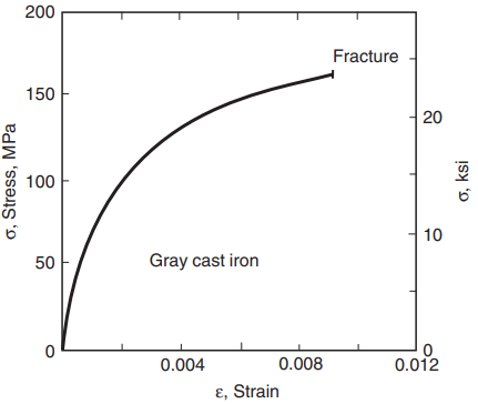
Stress–strain curves vary widely for different materials. Brittle behavior in a tension test is failure without extensive deformation. Gray cast iron, glass, and some polymers, such as PMMA (acrylic), are examples of materials with such behavior. A stress–strain curve for gray iron is shown in Fig. 4.
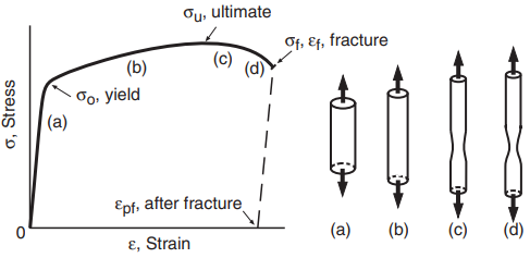
Other materials exhibit ductile behavior, failing in tension only after extensive deformation. Stress–strain curves for ductile behavior in engineering metals and some polymers are similar to Figs. 5 and 6, respectively.
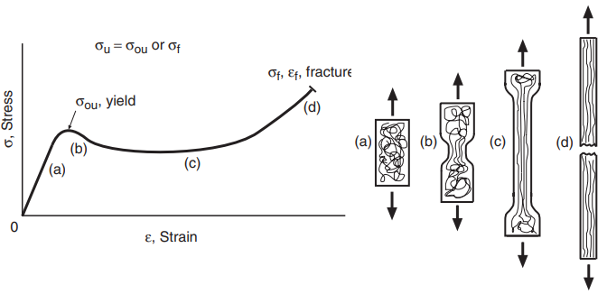
some polymers.
One might ask why we describe tension test results in terms of stress and strain, σ and ε, rather than simply force and length change, P and ΔL. Note that samples of a given material with different cross-sectional areas Ai will fail at higher forces for larger areas. By calculating the force per unit area, or stress, this effect of sample size is removed.
Hence, a given material is expected to have the same yield, ultimate, and fracture stress for any cross-sectional area Ai , while the corresponding forces P vary with Ai . (An actual experimental comparison for different Ai will be affected by minor variations in properties with location in the parent batch of material, lack of absolute precision in the laboratory measurements, and other such statistical errors.)
The use of strain ε similarly removes the effect of sample length. For a given stress, specimens with greater length L will exhibit a proportionately larger length change ΔL, but the strain ε corresponding to the yield, ultimate, and fracture points is expected to be the same for any length of sample. Hence, the stress–strain curve is considered to give a fundamental characterization of the behavior of the material.