Hardness Testing Methods
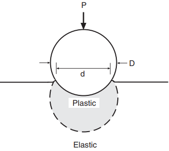
In engineering, hardness is most commonly defined as the resistance of a material to indentation. Indentation is the pressing of a hard round ball or point against the material sample with a known force so that a depression is made. The depression, or indentation, results from plastic deformation beneath the indenter, as shown in Fig. 1. Some specific characteristic of the indentation, such as its size or depth, is then taken as a measure of hardness.
Other principles are also used to measure hardness. For example, the Scleroscope hardness test is a rebound test that employs a hammer with a rounded diamond tip. This hammer is dropped from a fixed height onto the surface of the material being tested. The hardness number is proportional to the height of rebound of the hammer, with the scale for metals being set so that fully hardened tool steel has a value of 100. A modified version of this test is also used for polymers.
In mineralogy, the Mohs hardness scale is used. Diamond, the hardest known material, is assigned a value of 10. Decreasing values are assigned to other minerals, down to 1 for the soft mineral talc. Decimal fractions, such as 9.7 for tungsten carbide, are used for materials intermediate between the standard ones.
Where a material lies on the Mohs scale is determined by a simple manual scratch test. If two materials are compared, the harder one is capable of scratching the softer one, but not vice versa. This allows materials to be ranked as to hardness, and decimal values between the standard ones are assigned as a matter of judgment.
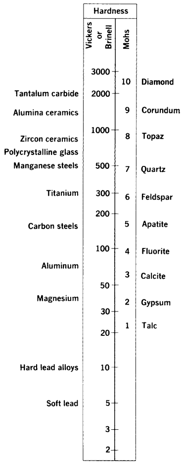
Very hard steels have a Mohs hardness around 7, and lower strength steels and other relatively hard metal alloys are generally in the range 4 to 5. Soft metals may be below 1, so their Mohs hardness is difficult to specify. Various materials are compared as to their Mohs hardness in Fig. 2. Also shown are values for two of the indentation hardness scales that will be discussed shortly.
Indentation hardness has an advantage over Mohs hardness in that the values obtained are less a matter of interpretation and judgment. There are a number of different standard indentation hardness tests. They differ from one another as to the geometry of the indenter, the amount of force used, etc. As time-dependent deformations may occur that affect the indentation, loading rates and/or times of application are fixed for each standard test.
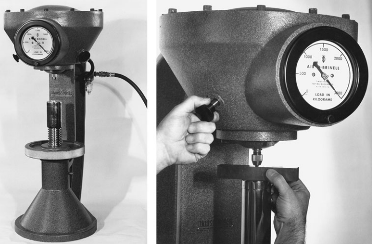
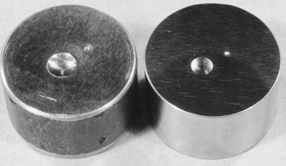
Test apparatus for the Brinell hardness test is shown in Fig. 3. Some of the resulting indentations are shown, along with those for Rockwell type tests, in Fig. 4. These two and the Vickers test are commonly used for engineering purposes.
Hardness Testing Methods
Brinell Hardness Test
In this test, a large steel ball—specifically, 10 mm in diameter—is used with a relatively high force. The force used is 3000 kg for fairly hard materials, such as steels and cast irons, and 500 kg for softer materials, such as copper and aluminum alloys. For very hard materials, the standard steel ball will deform excessively, and a tungsten carbide ball is used.
The Brinell hardness number, designated HB, is obtained by dividing the applied force P, in kilograms, by the curved surface area of the indentation, which is a segment of a sphere. This gives

where D is the diameter of the ball and d is the diameter of the indentation, both in millimeters, as illustrated in Fig. 1.
Vickers Hardness Test
The Vickers hardness test is based on the same general principles as the Brinell test. It differs primarily in that the indenter is a diamond point in the shape of a pyramid with a square base. The angle between the faces of the pyramid is α = 136◦, as shown in Fig. 5.
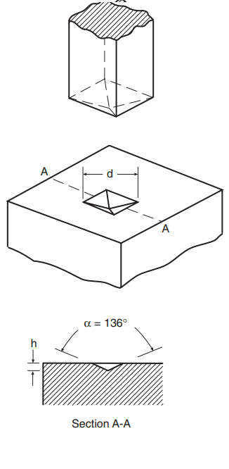
This shape results in the depth of penetration, h, being one-seventh of the indentation size, d, measured on the diagonal. The Vickers hardness number HV is obtained by dividing the applied force P by the surface area of the pyramidal depression. This yields

where d is in millimeters and P in kilograms.
Note that the standard pyramidal shape causes the indentations to be geometrically similar, regardless of their size. For reasons derived from plasticity theory and which are beyond the scope of the present discussion, this geometric similarity is expected to result in a Vickers hardness value that is independent of the magnitude of the force used.
Hence, a wide range of standard forces usually between 1 and 120 kg are used, so that essentially all solid materials can be included in a single wide-ranging hardness scale.
Ceramics and Glasses
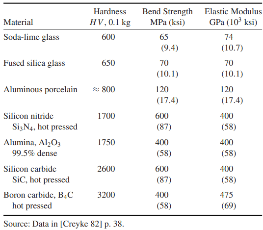
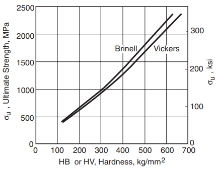
Approximate Vickers hardness numbers are given for various classes of materials in Fig. 2. Also, values for some ceramics are given in Table 1. Within the more limited range where the Brinell test can be used, there is approximate agreement with the Vickers scale. This approximate agreement is shown, by average curves for steels of various strengths, in Fig. 6.
Another hardness test that is somewhat similar to the Vickers test is the Knoop test. It differs in that the pyramidal indenter has a diamond-shaped base and in the use of the projected area to calculate hardness.
Rockwell Hardness Test
In the Rockwell test, a diamond point or a steel ball is employed as the indenter. The diamond point, called a Brale indenter, is a cone with an included angle of 120◦ and a slightly rounded end. Balls of sizes ranging between 1.6 mm and 12.7 mm are also used.
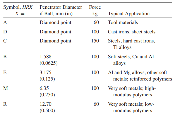
Various combinations of indenter and force are applied in the regular Rockwell test to accommodate a wide range of materials, as listed in Table 2. In addition, there is a superficial Rockwell hardness test that uses smaller forces and causes smaller indentations.
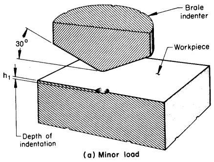
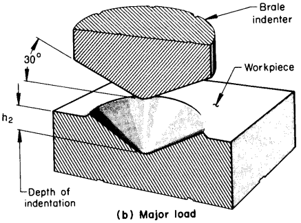
Rockwell tests differ from other hardness tests in that the depth of the indentation is measured, rather than the size. A small initial force called the minor load is first applied to establish a reference position for the depth measurement and to penetrate through any surface scale or foreign particles.
A minor load of 10 kg is used for the regular test. The major load is then applied, and the additional penetration due to the major load is measured. This is illustrated by the difference between h2 and h1 in Fig. 7.
Each Rockwell hardness scale has a maximum useful value around 100. An increase of one unit of regular Rockwell hardness represents a decrease in penetration of 0.002 mm. Hence, the hardness number is

where Δh = h2 − h1 is in millimeters and M is the upper limit of the scale. For regular Rockwell hardness, M = 100 for all scales using the diamond point (A, C, and D scales), and M = 130 for all scales using ball indenters (B, E, M, R, etc., scales).
The hardness numbers are designated HRX, where X indicates the scale involved, such as 60 HRC for 60 points on the C scale. Note that a Rockwell hardness number is meaningless unless the scale is specified. In practice, the hardness numbers are read directly from a dial on the hardness tester, rather than being calculated.
Hardness Correlations and Conversions
The deformations caused by a hardness indenter are of similar magnitude to those occurring at the ultimate tensile strength in a tension test. However, an important difference is that the material cannot freely flow outward, so that a complex triaxial state of stress exists under the indenter.
Nevertheless, empirical correlations can be established between hardness and tensile properties, primarily the ultimate tensile strength σu. For example, for low- and medium-strength carbon and alloy steels, σu can be estimated from Brinell hardness as
σu = 3.45(HB) MPa, σu = 0.50(HB) ksi ……(4)
where HB is assumed to be in units of kg/mm2. Note that we may also express hardness in units of MPa by applying the conversion factor 1 kg/mm2 = 9.807 MPa. If the same units (such as MPa) are used for both HB and σu, Eq. 4 becomes σu = 0.35(HB).
Observe that Eq. 4 approximates the curve shown in Fig. 6. However, there is considerable scatter in actual data, so this relationship should be considered to provide rough estimates only. For other classes of material, the empirical constant will differ, and the relationship may even become nonlinear.
Similarly, the relationship will change for a different type of hardness test. Rockwell hardness correlates well with σu and with other types of hardness test, but the relationships are usually nonlinear. This situation results from the unique indentation-depth basis of this test.
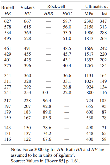
For carbon and alloy steels, a conversion chart for estimating various types of hardness from one another, and also ultimate tensile strength, is given as Table 3.
Numbers and Ultimate Tensile Strengths for
Carbon and Alloy Steels
More detailed conversion charts for steels and other metals are given in ASTM Standard No. E140, in various handbooks, and in information provided by manufacturers of hardness testing equipment.
Thanks for reading about “hardness testing methods”.