Deformation of Solids
There are three basic types of deformation: elastic, plastic, and creep deformation. Elastic deformation is discussed next, and this leads to some rough theoretical estimates of strength for solids.
Elastic Deformation
Elastic deformation is associated with stretching, but not breaking, the chemical bonds between the atoms in a solid. If an external stress is applied to a material, the distance between the atoms changes by a small amount that depends on the material and the details of its structure and bonding. These distance changes, when accumulated over a piece of material of macroscopic size, are called elastic deformations. If the atoms in a solid were very far apart, there would be no forces between them.
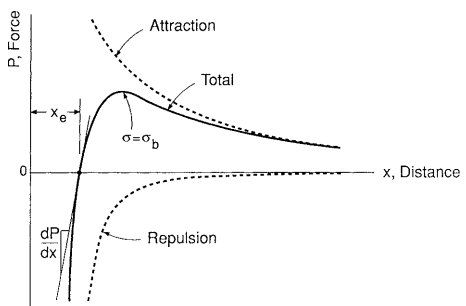
As the distance x between atoms is decreased, they begin to attract one another according to the type of bonding that applies to the particular case. This is illustrated by the upper curve in Fig. 1.
A repulsive force also acts that is associated with resistance to overlapping of the electron shells of the two atoms. This repulsive force is smaller than the attractive force at relatively large distances, but it increases more rapidly, becoming larger at short distances. The total force is thus attractive at large distances, repulsive at short distances, and zero at one particular distance xe, which is the equilibrium atomic spacing. This is also the point of minimum potential energy.
Elastic deformations of engineering interest usually represent only a small perturbation about the equilibrium spacing, typically less than 1% strain. The slope of the total force curve over this small region is approximately constant.
Let us express force on a unit area basis as stress, σ = P/A, where A is the cross-sectional area of material per atom. Also, note that strain is the ratio of the change in x to the equilibrium distance xe.
Since the elastic modulus E is the slope of the stress–strain relationship, we have

Hence, E is fixed by the slope of the total force curve at x = xe, which is illustrated in Fig. 1.
Trends in Elastic Modulus Values
Strong primary chemical bonds are resistant to stretching and so result in a high value of E. For example, the strong covalent bonds in diamond yield a value around E = 1000 GPa, whereas the weaker metallic bonds in metals give values generally within a factor of three of E = 100 GPa.
In polymers, E is determined by the combination of covalent bonding along the carbon chains and the much weaker secondary bonding between chains. At relatively low temperatures, many polymers exist in a glassy or crystalline state.
The modulus is then on the order of E = 3 GPa, but it varies considerably above and below this level, depending on the chain-molecule structure and other details. If the temperature is increased, thermal activation provides increased free volume between chain molecules, permitting motion of increased lengths of chain.
A point is reached where large scale motions become possible, causing the elastic modulus to decrease, often dramatically. This trend is shown for polystyrene in Fig. 2.
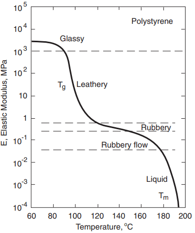
The temperature where the rapid decrease in E occurs varies for different polymers and is called the glass transition temperature, Tg. Melting does not occur until the polymer reaches a somewhat higher temperature, Tm, provided that chemical decomposition does not occur first.
Above Tg, the elastic modulus may be as low as E = 1 MPa. Viscous flow is now prevented only by tangling of the long chain molecules and by the secondary bonds in any crystalline regions of the polymer.
A polymer has a leathery or rubbery character above its Tg, as do vulcanized natural rubber and synthetic rubbers at room temperature. For single crystals, E varies with the direction relative to the crystal structure; that is, crystals are more resistant to elastic deformation in some directions than in others.
But in a polycrystalline aggregate of randomly oriented grains, an averaging effect occurs, so that E is the same in all directions. This latter situation is at least approximated for most engineering metals and ceramics.
Theoretical Strength
A value for the theoretical cohesive strength of a solid can be obtained by using solid-state physics to estimate the tensile stress necessary to break primary chemical bonds, which is the stress σb corresponding to the peak value of force in Fig. 1.
These values are on the order of σb = E/10 for various materials. Hence, for diamond, σb ≈ 100 GPa, and for a typical metal, σb ≈ 10 GPa. Rather than the bonds being simply pulled apart in tension, another possibility is shear failure. A simple calculation can be done to obtain an estimate of the theoretical shear strength.
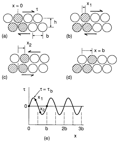
Consider two planes of atoms being forced to move slowly past one another, as in Fig. 3. The shear stress τ required first increases rapidly with displacement x, then decreases and passes through zero as the atoms pass opposite one another at the unstable equilibrium position x = b/2. The stress changes direction beyond this as the atoms try to snap into a second stable configuration at x = b. A reasonable estimate is a sinusoidal variation

where τb is the maximum value as τ varies with x; hence, it is the theoretical shear strength. The initial slope of the stress–strain relationship must be the shear modulus, G, in a manner analogous to E for the tension case previously discussed. Noting that the shear strain for small values of displacement is γ = x/h, we have

Obtaining dτ/dx from Equation 1 and substituting its value at x = 0 gives τb:
τb = Gb/2πh
The ratio b/h varies with the crystal structure and is generally around 0.5 to 1, so this estimate is on the order of G/10.
σb = 2τb = Gb/πh
In a tension test, the maximum shear stress occurs on a plane 45◦ to the direction of uniaxial stress and is half as large. Thus, a theoretical estimate of shear failure in a tension test is
Since G is in the range E/2 to E/3, this estimate gives a value similar to the previously mentioned σb = E/10 estimate based on the tensile breaking of bonds.
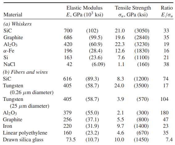
Theoretical tensile strengths around σb = E/10 are larger than the actual strengths of solids by a large amount, typically by a factor of 10 to 100. This discrepancy is thought to be due mainly to the imperfections present in most crystals, which decrease the strength. However, small whiskers can be made that are nearly perfect single crystals.
Also, thin fibers and wires may have a crystal structure such that strong chemical bonds are aligned with the length direction. Tensile strengths in such cases are indeed much higher than for larger and more imperfect samples of material. Strengths in the range from E/100 to E/20, corresponding to one-tenth to one-half of the theoretical strength, have been achieved in this way, lending credence to the estimates. Some representative data are given in following Table.
Plastic Deformation of Solids
Elastic deformation involves the stretching of chemical bonds. When the stress is removed, the deformation disappears. More drastic events can occur which have the effect of rearranging the atoms so that they have new neighbors after the deformation is complete. This causes an inelastic deformation that does not disappear when the stre
Inelastic deformation that occurs almost instantaneously as the stress is applied is called plastic deformation, as distinguished from creep deformation, which occurs only after passage of time under stress.
Plastic Deformation by Dislocation Motion
Single crystals of pure metals that are macroscopic in size and which contain only a few dislocations are observed to yield in shear at very low stresses. For example, for iron and other BCC metals, this occurs around τo = G/3000, that is, about τo = 30 MPa. For FCC and HCP metals, even lower values are obtained around τo = G/100,000, or typically τo = 0.5 MPa.
Thus, shear strengths for imperfect crystals of pure metals can be lower than the theoretical value for a perfect crystal of τb = G/10 by at least a factor of 300 and sometimes by as much as a factor of 10,000.
This large discrepancy can be explained by the fact that plastic deformation occurs by motion of dislocations under the influence of a shear stress, as illustrated in Fig. 1.
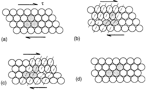
As a dislocation moves through the crystal, plastic deformation is, in effect, proceeding one atom at a time, rather than occurring simultaneously over an entire plane.
This incremental process can occur much more easily than simultaneous breaking of all the bonds, as assumed in the theoretical shear strength calculation for a perfect crystal.
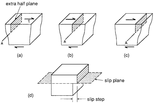
The deformation resulting from dislocation motion proceeds for edge and screw dislocations, as illustrated in Fig. 2 and Fig. 3, respectively.
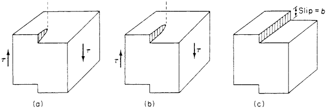
The plane in which the dislocation line moves is called the slip plane, and where the slip plane intersects a free surface, a slip step is formed. Since dislocations in real crystals are usually curved and thus have both edge and screw character, plastic deformation actually occurs by a combination of the two types of dislocation motion.
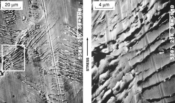
Plastic deformation is often concentrated in bands called slip bands. These are regions where the slip planes of numerous dislocations are concentrated; hence, they are regions of intense plastic shear deformation separated by regions of little shear. Where slip bands intersect a free surface, steps are formed as a result of the combined slip steps of numerous dislocations. (See Fig. 4.)
For a given crystal structure, such as BCC, FCC, or HCP, slip is easier on certain planes, and within these planes in certain directions. For metals, the most common planes and directions are shown in Fig. 5. The preferred planes are those on which the atoms are relatively close together, called close-packed planes, such as the basal plane for the HCP crystal.
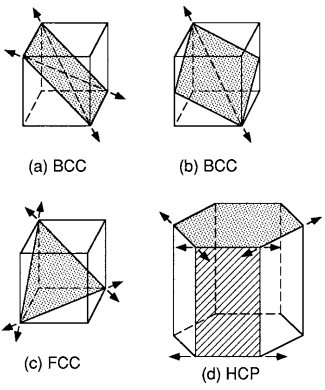
Similarly, the preferred slip directions within a given plane are the close-packed directions in which the distances between atoms is smallest. This is the case because a dislocation can more easily move if the distance to the next atom is smaller. Also, atoms in adjacent planes project less into the spaces between atoms in the close-packed planes than in other planes, so there is less interference with slip displacement.
Discussion of Plastic Deformation
The result of plastic deformation (yielding) is that atoms change neighbors and return to a stable configuration with new neighbors after the dislocation has passed. Note that this is a fundamentally different process than elastic deformation, which is merely the stretching of chemical bonds.
Elastic deformation occurs as an essentially independent process along with plastic deformation. When a stress that causes yielding is removed, the elastic strain is recovered just as if there had been no yielding, but the plastic strain is permanent.
Metals used in load-resisting applications have strengths considerably above the very low values observed in crystals of pure metals with some defects, but not nearly as high as the very high theoretical value for a perfect crystal. This is illustrated in Fig. 6 for irons and steels, which are composed mostly of iron.
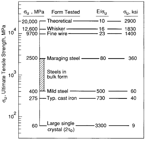
If there are obstacles that impede dislocation motion, the strength may be increased by a factor of 10 or more above the low value for a pure metal crystal. Grain boundaries have this effect, as does a second phase of hard particles dispersed in the metal. Alloying also increases strength, as the different-sized atoms make dislocation motion more difficult.
If a large number of dislocations are present, these interfere with one another, forming dense tangles and blocking free movement. In nonmetals and compounds where the chemical bonding is covalent or partially covalent, the directional nature of the bonds makes dislocation motion difficult.
Materials in this class include the crystals of carbon, boron, and silicon, and also intermetallic compounds and compounds formed between metals and nonmetals, such as metal carbides, borides, nitrides, oxides, and other ceramics.
At ambient temperatures, these materials are hard and brittle and do not generally fail by yielding due to dislocation motion. Instead, the strength falls below the high theoretical value for a perfect crystal mainly because of the weakening effect of small cracks and pores that are present in the material. However, some dislocation motion does occur, especially for temperatures above about half of the (usually high) melting temperature, where Tm is measured relative to absolute zero.
Creep Deformation
In addition to elastic and plastic deformation as already described, materials deform by mechanisms that result in markedly time-dependent behavior, called creep. Under constant stress, the strain varies with time, as shown in Fig. 7.
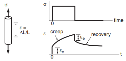
There is an initial elastic deformation εe, and following this, the strain slowly increases as long as the stress is maintained. If the stress is removed, the elastic strain is quickly recovered, and a portion of the creep strain may be recovered slowly with time; the rest remains as permanent deformation.
In crystalline materials—that is, in metals and ceramics—one important mechanism of creep is diffusional flow of vacancies. Spontaneous formation of vacancies is favored near grain boundaries that are approximately normal to the applied stress and is disfavored for parallel ones.
This results in an uneven distribution of vacancies and in vacancies diffusing, or moving, from regions of high concentration to regions of low concentration, as illustrated in Fig. 8.
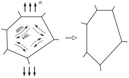
As indicated, movement of a vacancy in one direction is equivalent to movement of an atom in the opposite direction. The overall effect is a change in the shape of the grain, contributing to a macroscopic creep strain.
Some other creep mechanisms that operate in crystalline materials include special dislocation motions that can circumvent obstacles in a time-dependent manner. There may also be sliding of grain boundaries and the formation of cavities along grain boundaries.
Creep behavior in crystalline materials is strongly temperature dependent, typically becoming an important engineering consideration around 0.3 to 0.6Tm, where Tm is the absolute melting temperature.
Different creep mechanisms operate in amorphous (noncrystalline) glasses and in polymers. One of these is viscous flow in the manner of a very thick liquid. This occurs in polymers at temperatures substantially above the glass transition temperature Tg and approaching Tm. The chainlike molecules simply slide past one another in a time-dependent manner. Around and below Tg, more complex behavior involving segments of chains and obstacles to chain sliding become important. In this case, much of the creep deformation may disappear slowly (recover) with time after removal of an applied stress, as illustrated in Fig. 7.
Creep is a major limitation on the engineering application of any polymer above its Tg, which is generally in the range −100 to 200◦C for common polymers.