Viscoelastic Behavior of Materials
The previous discussion assumed that the strain was an immediate response to stress. This is an assumption for elastic and elastoplastic materials. However, no material has this property under all conditions.
In some cases, materials exhibit both viscous and elastic responses, which are known as viscoelastic. Typical viscoelastic materials used in construction applications are asphalt and plastics.
Time Dependent Response of Materials
Viscoelastic materials have a delayed response to load application.
For example, Figure 1(a) shows a sinusoidal axial load applied on a viscoelastic material, such as asphalt concrete, versus time. Figure 1(b) shows the resulting deformation versus time, where the deformation lags the load—that is, the maximum deformation of the sample occurs after the maximum load is applied.
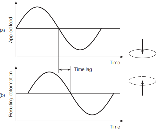
material.
The amount of time delayed of the deformation depends on the material characteristics and the temperature. The delay in the response of viscoelastic materials can be simulated by the movement of the Slinky® toy in the hand of a child, as illustrated in Figure 2.
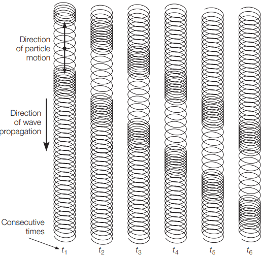
waves in a Slinky®.
As the child moves her hand up and down, waves of compression and dilation are developed in the Slinky. However, the development of the waves in the Slinky does not happen exactly at the same time as the movements of the child’s hand.
For example, a compression wave could be propagating in one part of the Slinky at the same time when the child is moving her hand upward and vice versa. This occurs because of the delay in response relative to the action.
Typical viscoelastic civil engineering materials, such as asphalt, have the same behavior, although they are not as flexible as a Slinky. There are several mechanisms associated with time-dependent deformation, such as creep and viscous flow. There is no clear distinction between these terms.
Creep is generally associated with long-term deformations and can occur in metals, ionic and covalent crystals, and amorphous materials.
On the other hand, viscous flow is associated only with amorphous materials and can occur under short-term load duration. For example, concrete, a material with predominantly covalent crystals, can creep over a period of decades.
Asphalt concrete pavements, an amorphous-binder material, can have ruts caused by the accumulated effect of viscous flows resulting from traffic loads with a load duration of only a fraction of a second.
Creep of metals is a concern at elevated temperatures. Steel can creep at temperatures greater than 30% of the melting point on the absolute scale. This can be a concern in the design of boilers and nuclear reactor containment vessels. Creep is also considered in the design of wood and advanced composite structural members. Wood elements loaded for a few days can carry higher stresses than elements designed to carry “permanent” loads.
On the other hand, creep of concrete is associated with microcracking at the interface of the cement paste and the aggregate particles. The viscous flow models are similar in nature to Hooke’s law. In linearly viscous materials, the rate of deformation is proportional to the stress level. These materials are not compressible and do not recover when the load is removed. Materials with these characteristics are Newtonian fluids.
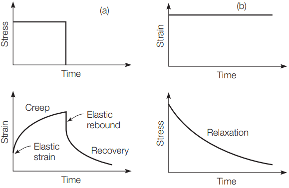
(b) relaxation.
Figure 3(a) shows a typical creep test in which a constant compressive stress is applied to an asphalt concrete specimen. In this case, an elastic strain will develop, followed by time-dependent strain or creep. If the specimen is unloaded, a part of the strain will recover instantaneously, while the remaining strain will recover, either completely or partially, over a period of time.
Another phenomenon typical of time-dependent materials is relaxation, or dissipation of stresses with time. For example, if an asphalt concrete specimen is placed in a loading machine and subjected to a constant strain, the stress within the specimen will initially be high, then gradually dissipate due to relaxation as shown in Figure 3(b).
Relaxation is an important concern in the selection of steel for a prestressed concrete design. In viscoelasticity, there are two approaches used to describe how stresses, strains, and time are interrelated.
One approach is to postulate mathematical relations between these parameters based on material functions obtained from laboratory tests. The other approach is based on combining a number of discrete rheological elements to form rheological models, which describe the material response.
Rheological Models of Materials
Rheological models are used to model mechanically the timedependent behavior of materials. There are many different modes of material deformation, particularly in polymer materials. These materials cannot be described as simply elastic, viscous, etc.
However, these materials can be modeled by a combination of simple physical elements. The simple physical elements have characteristics that can be easily visualized. Rheology uses three basic elements, combined in either series or parallel to form models that define complex material behaviors. The three basic rheological elements, Hookean, Newtonian, and St. Venant, are shown in Figure 4.
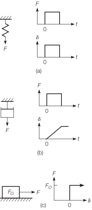
The Hookean element, as in Figure 4(a), has the characteristics of a linear spring. The deformation d is proportional to force F by a constant M:
F = Mδ ………(Equation 1)
This represents a perfectly linear elastic material. The response to a force is instantaneous and the deformation is completely recovered when the force is removed. Thus, the Hookean element represents a perfectly linear elastic material. A Newtonian element models a perfectly viscous material and is modeled as a dashpot or shock absorber as seen in Figure 4(b).
The deformation for a given level of force is proportional to the amount of time the force is applied. Hence, the rate of deformation, for a constant force, is a constant β:
F = βδ ………(Equation 2)
The dot above the δ defines this as the rate of deformation with respect to time. If β = 0 at time t = 0 when a constant force F is applied, the deformation at time t is
δ = Ft/β ………(Equation 3)
When the force is removed, the specimen retains the deformed shape. There is no recovery of any of the deformation.
The St. Venant element, as seen in Figure 4(c), has the characteristics of a sliding block that resists movement by friction. When the force F applied to the element is less than the critical force FO, there is no movement.
If the force is increased to overcome the static friction, the element will slide and continue to slide as long as the force is applied. This element is unrealistic, since any sustained force sufficient to cause movement would cause the block to accelerate. Hence, the St. Venant element is always used in combination with the other basic elements. The basic elements are usually combined in parallel or series to model material response.
(c) Prandtl.
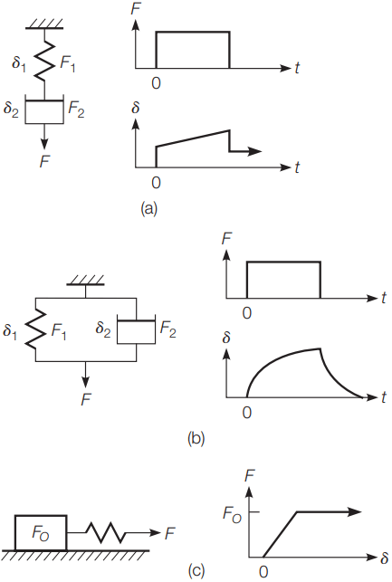
Figure 5 shows the three primary two-component models: the Maxwell, Kelvin, and Prandtl models. The Maxwell and Kelvin models have a spring and dashpot in series and parallel, respectively. The Prandtl model uses a spring and St. Venant elements in series.
In the Maxwell model [Figure 5(a)], the total deformation is the sum of the deformations of the individual elements. The force in each of the elements must be equal to the total force (F = F1 = F2). Thus, the equation for the total deformation at any time after a constant load is applied is simply:
δ = δ1 + δ2 = F/M + Ft/β ………(Equation 4)
In the Kelvin model, Figure 5(b), the deformation of each of the elements must be equal at all times due to the way the model is formulated. Thus, the total deformation is equal to the deformation of each element (δ = δ1 = δ2). Since the elements are in parallel, they will share the force such that the total force is equal to the sum of the force in each element.
If δ = 0 at time t = 0 when a constant force F is applied, Equation 1, then requires zero force in the spring. Hence, when the load is initially applied, before any deformation takes place, all of the force must be in the dashpot. Under constant force the deformation of the dashpot must increase since there is force on the element.
However, this also requires deformation of the spring, indicating that some of the force is carried by the spring. In fact, with time the amount of force in the dashpot decreases and the force in the spring increases. The proportion is fixed by the fact that the sum on the forces in the two elements must be equal to the total force.
After a sufficient amount of time, all of the force will be transferred to the spring and the model will stop deforming. Thus the maximum deformation of the Kelvin model is δ = F/M. Mathematically, the equation for the deformation in a Kelvin model is derived as:
F = F1 + F2 = Mδ + βδ ………(Equation 5)
Integrating Equation 5, using the limits that δ= 0 at t = 0, and solving for the deformation δ at time t results in
δ = (F/M)(1 – e-Mt/β) ………(Equation 6)
The Prandtl model [Figure 5(c)] consists of St. Venant and Hookean bodies in series. The Prandtl model represents a material with an elastic–perfectly plastic response. If a small load is applied, the material responds elastically until it reaches the yield point, after which the material exhibits plastic deformation.
Neither the Maxwell nor Kelvin model adequately describes the behavior of some common engineering materials, such as asphalt concrete.
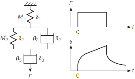
However, the Maxwell and the Kelvin models can be put together in series, producing the Burgers model, which can be used to describe simplistically the behavior of asphalt concrete.
viscoelastic materials.
As shown in Figure 6, the Burgers model is generally drawn as a spring in series with a Kelvin model in series with a dashpot. The total deformation at time t, with an initial point of δ = 0 at time t = 0, is then the sum of the deformations at time t of these three elements.

The deformation-time diagram for the loading part of the Burgers model demonstrates three distinct phases of behavior.
First is the instantaneous deformation of the spring when the load is applied. Second is the combined deformation of the Kelvin model and the dashpot.
Third, after the Kelvin model reaches maximum deformation, there is a continued deformation of the dashpot at a constant rate of deformation. The unloading part of the Burgers model follows similar behavior.
Some materials require more complicated rheological models to represent their response. In such cases, a number of Maxwell models can be combined in parallel to form the generalized Maxwell model, or a number of Kelvin models in series can be used to form the generalized Kelvin model.
The use of rheological models requires quantifying material parameters associated with each model. Laboratory tests, such as creep tests, can be used to obtain deformation–time curves from which material parameters can be determined.
Although the rheological models are useful in describing the time-dependent response of materials, they can be used only to represent uniaxial responses. The three-dimensional behavior of materials and the Poisson’s effect cannot be represented by these models.