Theodolite is an instrument which replaced compass and level. It can measure both horizontal and vertical angles. If telescope is kept at zero reading of vertical angle it serves as an ordinary level. In this modern era of electronics equipments have come up to measure the distances to relieve surveyor from chaining long lines.
It is a commonly used instrument for measuring horizontal and vertical angles. It is used for prolonging a line, levelling and even for measuring the distances indirectly (techeometry). Using verniers angles can be read accurately up to 20″.
Construction of Vernier Theodolite
Precise theodolites are available which can read angles up to even 1″ accuracy. They use optical principle for more accurate instruments. Now-a-days electronic theodolites are also available which display the angles. In this article construction and use of vernier theodolite is explained.
Parts of a Vernier Theodolite
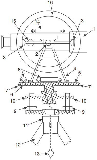
Figure 1(a) shows a sectional view of a typical vernier theodolite and Fig. 1(b) shows photograph of such theodolite. Main parts of such a theodolite are:
1. Telescope 2. Trunnian axis 3. Vernier frame 4. Standards or A-Frame 5. Upper plate 6. Lower plate 7. Vernier
8. Plate level 9. Foot crews 10. Levelling head 11. Tripod head 12. Tripod 13. Plumb bob 14. Altitude level 15. Focussing screw 16. Vertical circle
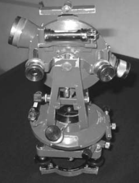
1. Telescope: A telescope is mounted on a horizontal axis (trunnian axis) hence it can rotate in vertical plane. Its length varies from 100 mm 175 mm and its diameter is 38 mm at objective end. Its function is to provide a line of sight.
2. Vertical Circle: A vertical circle graduated up to an accuracy of 20′ is rigidly connected to the telescope and hence moves with it when the telescope is rotated in vertical plane. The graduations are in quadrantal system, 0-0 line being horizontal (Ref. Fig. 2).

3. Vernier Frame: It is a T-shaped frame (Fig. 3) consisting of a vertical arm and a horizontal arm. With the help of the climping screws the vertical frame and hence the telescope can be clamped at desired angle. Vertical frame is also known as T-frame or index frame.
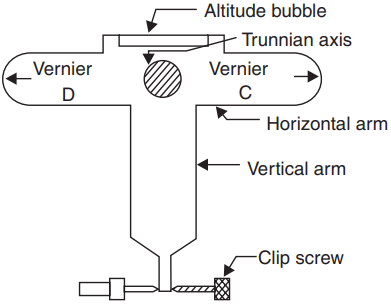
The vernier arm is known as index arm. At the ends it carries verniers C and D so as to read graduations on vertical circle. They are provided with glass magnifiers. Altitude bubble tube is fitted over the horizontal arm.
4. Standards or A-Frame: The frames supporting telescope are in the form of English letter ‘A’. This frame allows telescope to rotate on its trunnian axis in vertical frame. The T-frame and the clamps are also fixed to this frame.
5. Upper Plate [Fig. 4]: Upper plate supports standards on its top surface. On lower side it is attached to a inner spindle which rotates in the outer spindle of lower plate. Using upper clamp, upper plate can be clamped to lower plate.
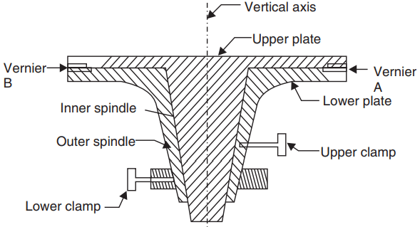
Using tangent screws, it is possible to give slight relative motion between the two plates, even after clamping. Two diametrically opposite verniers A and B fixed to upper plate help in reading horizontal circle graduations. They are provided with magnifying glasses.
6. Lower Plate: The lower plate, attached to the outer spindle carries a graduated circle at its bevelled edge. Graduations are up to an accuracy of 20′. It can be clamped at any desired position using lower clamps. If upper clamp is locked and the lower one is loosened the two plates rotate together. If the upper clamp is loosened and lower clamp locked, upper plate alone rotates. This mechanism is utilised in measuring horizontal angle.
7. Plate Level: One or two plate level tubes are mounted on the upper plate. If the two level tubes are provided they will be at right angles to each other one of them being parallel to trunnion axis. These levels help in making the vertical axis of the instrument truely vertical.
8. Levelling Head: It consists of two parallel triangular plates known as tribratch plates. The upper tribratch plate is provided with three levelling screws—each one carried by a arm of tribratch plate. By operating screws the levelling of upper plate and hence telescope can be ensured. The lower tribratch can be fitted into a tripod head.
9. Tripod: Theodolite is always used by mounting it on a tripod. The legs of tripod may be solid or framed. At the lower end the legs are provided with steel shoes to get good grip with the ground. The top of tripod is provided with external screw to which the lower tribratch plate can be screwed. When not in use tripod head may be protected with a steel cap, provided for this purpose.
10. Plumb Bob: A hook is provided at the middle of lower tribratch plate from which a plumb bob can be suspended. It facilitates exact centering of the theodolite on a station.
11. Shifting Head: It is provided below the lower plate. In this, one plate slides over another over a small area of about 10 mm radius. The two plates can be tightened in the desired position. It facilitates exact centering of the instruments.
12. Magnetic Compass: In some theodolites a magnetic compass is fixed on one of the strands. It is useful if readings are to be recorded with magnetic north as meridian.
Use of Theodolite
Theodolite is used for measuring horizontal and vertical angles. For this the theodolite should be centered on the desired station point, levelled and telescope is focussed. This process of centering, levelling and focussing is called temporary adjustment of the instrument.
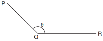
The procedure is explained for measuring horizontal angle θ = PQR at station Q (Ref. Fig. 5)
- Set the theodolite at Q with vertical circle to the left of the line of sight and complete all temporary adjustments.
- Release both upper and lower clamps and turn upper plate to get 0° on the main scale. Then clamp main screw and using tangent screw get exactly zero reading. At this stage vernier A reads 0° and vernier B reads 180°.
- Through telescope take line of sight to signal at P and lock the lower clamp. Use tangent screw for exact bisection.
- Release the upper clamp and swing telescope to bisect signal at R. Lock upper clamp and use tangent screen to get exact bisection of R.
- Read verniers A and B. The reading of vernier A gives desired angle PQR directly, while 180° is to be subtracted from the reading of vernier B to get the angle PQR.
- Transit (move by 180° in vertical plane) the telescope to make vertical circle to the right of telescope. Repeat steps 2 to 5 to get two more values for the angle.
- The average of 4 values found for θ, give the horizontal angle. Two values obtained with face left and two obtained with face right position of vertical circle are called one set of readings.
- If more precision is required the angle may be measured repeatedly. i.e., after step 5, release lower clamp, sight signal at P, then lock lower clamp, release upper clamp and swing the telescope to signal at Q. The reading of vernier A doubles. The angle measured by vernier B is also doubled. Any number of repetitions may be made and average taken. Similar readings are then taken with face right also. Finally average angle is found and is taken as desired angle ‘Q’. This is called method of repetition.
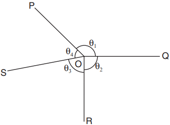
- There is another method of getting precise horizontal angles. It is called method of reiteration. If a number of angles are to be measured from a station this technique is used (Fig. 6). With zero reading of vernier A signal at P is sighted exactly and lower clamp and its tangent screw are locked. Then θ1 is measured by sighting Q and noted. Then θ2, θ3 and θ4 are measured by unlocking upper clamp and bisecting signals at R, S and P. The angles are calculated and checked to see that sum is 360º. In each case both verniers are read and similar process is carried out by changing the face (face left and face right).
Measurement of Vertical Angle
Horizontal sight is taken as zero vertical angle. Angle of elevations are noted as +ve angles and angle of depression as –ve angles. To measure vertical angle the following procedure may be followed:
- Complete all temporary adjustment at the required station.
- Take up levelling of the instrument with respect to altitude level provided on the A – frame. This levelling process is similar to that used for levelling dumpy level i.e., first altitude level is kept parallel to any two levelling screws and operating those two screws bubble is brought to centre. Then by rotating telescope, level tube is brought at right angles to the original position and is levelled with the third screw. The procedure is repeated till bubble is centred in both positions.
- Then loosen the vertical circle clamp, bisect P and lock the clamp. Read verniers C and D to get vertical angle. Take the average as the actual vertical angle.
Electromagnetic Distance Measuring Instruments
Sun light or artificially generated electromagnetic waves consist of waves of different lengths. The spectrum of an electromagnetic wave is as shown below:
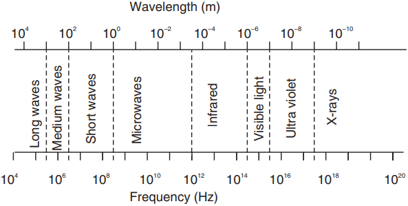
Among these waves microwaves, infrared waves and visible light waves are useful for the distance measurement. In EDM instruments these waves are generated, modulated and then propagated. They are reflected at the point up to which distance is to be measured from the instrument station and again received by the instrument. The time taken by the wave to travel this 2x distance may be measured and knowing the velocity of wave, the distance may be calculated.
However time is too short, measuring the time taken is difficult. The improved techniques use phase difference method in which the number of completed wave and incomplete wave is measured. Knowing the length of wave, distances are calculated. Built up microprocessors provided in the instrument calculate the distances and display it by liquid crystal display (LCD).
EDM instruments may be classified into the following three types:
1. Micro wave instruments 2. Infrared wave instruments 3. Light wave instruments.
Micro Wave Instruments
These instruments make use of micro waves. Such instruments were invented as early as 1950 in South Africa by Dr. T.L. Wadley and named them as Tellurometers.
The instrument needs only 12 to 24 V batteries. Hence they are light and highly portable. Tellurometers can be used in day as well as in night. The range of these instruments is up to 100 km. It consists of two identical units.
One unit is used as master unit and the other as remote unit. Just by pressing a button, a master unit can be converted into a remote unit and a remote unit into a master unit. It needs two skilled persons to operate. A speech facility is provided to each operator to interact during measurements.
Infrared Wave Instruments
In these instruments amplitude modulated infrared waves are used. Prism reflectors are used at the end of line to be measured. These instruments are light and economical and can be mounted on theodolite. With these instruments accuracy achieved is ± 10 mm. The range of these instruments is up to 3 km.
These instruments are useful for most of the civil engineering works. These instruments are available in the trade names DISTOMAT DI 1000 and DISTOMAT DI 55. 16.2.3 Light Wave Instruments These instruments rely on propagation of modulated light waves. This type of instrument was first developed in Sweden and was named as Geodimeter. During night its range is up to 2.5 km while in day its range is up to 3 km.
Accuracy of these instruments varies from 0.5 mm to 5 mm/km distance. These instruments are also very useful for civil engineering projects. The advantage of using EDM instruments is the speed and accuracy in measurement. Several obstacles to chaining are automatically overcome when these instruments are used.
Total Station
To decrease the length of this web page, content of this section is placed on another web page. To access that page, please follow the link.
Global Positioning System
The station points used in surveying are to be identified before executing any project. For this purpose, surveyors used permanent objects as reference points and made reference sketches of station points. Navigators used sun and stars as references.
Sometimes when the project is taken up the so called permanent object (like building corner) may not exist when the execution of project work is taken up. For navigations weather conditions may obstruct the observations.
Now-a-days this problem is overcome by using an instrument called Global Positioning System (GPS). This was developed by United States defence department and was called as Navigational System with Time and Ranging Global Positioning System (NAVSTAR) or which is now simply known as GPS.
There are 24 geostationary satellites positioned around the earth by US air force. These satellites are used as reference points to locate any point on the earth. These satellites are at an altitude of 20200 km above the earth. The 24 satellites are positioned such that from any point on the earth a minimum of 4 satellites are visible.
A user needs only GPS receiver. The receiver measures the travel time of the signals from satellites and calculate position (latitude and longitude) and the elevation altitude of the station with reference to a selected datum.
The advantages of using GPS are:
- Can be used in day as well as in night.
- Intervisibility of the two stations on the earth is not a requirement.
- Time required to establish the position of a point is much less.
- Man power required is less.
- Accuracy is high. Most expensive GPS provide accuracies within 10 mm.
Uses of GPS
GPS is very useful in
- Marine navigation
- Airborne aviation
- Surveying of land.
- Sports such as yatching, hiking.
- The sophistication of GPS has improved so much that drivers of automobiles can get directions to their destinations easily on the screen.