There are a wide variety of methods and techniques available for the non-destructive testing of structural concrete, which can be broadly divided into those that assess the concrete itself, and those which are concerned with locating and determining the condition of the steel embedded in it.
We are going to describe three well-established tests for concrete that are strictly non-destructive, more briefly discuss others that involve some minor damage to the concrete – the so-called partially destructive tests – and then list and briefly comment on some other methods. We do not have space to consider tests to assess the location and condition of reinforcing and prestressing steel, important though these are.
Non-destructive Testing of Concrete
Non-destructive testing of concrete is used for two main purposes:
- In laboratory studies, where it is particularly useful for repeated testing of the same specimen to determine the change of properties with time, for example to provide information on degradation in different environments.
- In in-situ concrete, to assess:
- strength development, where this is critical for the construction sequence
- compliance with specifications, particularly where the concrete has under performed or been deemed ‘unfit for purpose’
- the residual strength after damage, e.g. by fire or overload
- the cause of degradation or deterioration, often long term, associated with the durability issues
- strength when a change of use is proposed.
Two of the tests that we will describe, the rebound hammer and ultrasonic pulse velocity, are commonly used for both these purposes; the third, the resonant frequency test, can only be used on prepared specimens in the laboratory.
An estimation of the strength of concrete is often required, and therefore the degree of correlation of the non-destructive test measurement(s) with strength is important, and will be discussed in each case.
It will be apparent that a single non-destructive test rarely gives a single definitive answer, and engineering judgement is required in interpreting the results. Nevertheless, the usefulness of such tests will become apparent.
Surface Hardness – Rebound (or Schmidt) Hammer Test
This is perhaps the simplest of the commonly available tests, and can be used on laboratory specimens or on in-situ concrete. Its use in Europe is covered by BS EN 12504-2. The apparatus is contained in a hand-held cylindrical tube, and consists of a spring-loaded mass that is fired with a constant energy against a plunger held against the surface of the concrete (Fig. 1).
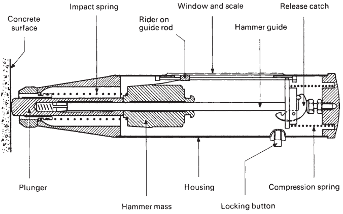
The amount of rebound of the mass expressed as the percentage of the initial extension of the spring is shown by the position of a rider on a graduated scale, and recorded as the rebound number. Less energy is absorbed by a harder surface, and so the rebound number is higher.
A smooth concrete surface is required, but even then there is considerable local variation due to the presence of coarse aggregate particles (giving an abnormally high rebound number) or a void (giving a low number) just below the surface, and therefore a number of readings must be taken and averaged.
Typical recommendations are for at least nine readings over an area of 300 mm2 , no two readings being taken within 25 mm of each other or from an edge. Also, the concrete being tested must be part of an unyielding mass; laboratory specimens such as cubes should therefore be held under a stress of about 7 MPa in a compressiontesting machine.
The test clearly only measures the properties of the surface zone of the concrete, to a depth of about 25 – 30 mm. Although the hardness of the concrete cannot in principle be directly related to any other single property, calibrations tests produce empirical correlations with strength that depend on:
- the aggregate type
- the moisture condition of the surface
- the angle of the hammer with the vertical, which will vary since the test must be carried out with the plunger normal to the surface of the concrete.
rebound test results (UCL data).
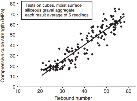
There is therefore no single universal correlation. Figure 2 shows the relationship between rebound number and strength obtained by students at UCL in laboratory classes over several years.
The degree of scatter is somewhat higher than that reported by other workers, the most likely explanation being the inexperience of the operatives. Even with more skilful operatives, strength cannot be predicted with great certainty, but the test is very simple and convenient, and so is often used as a first step in an investigation of in-situ concrete, for example to assess uniformity or to compare areas of known good quality and suspect concrete.
Ultrasonic Pulse Velocity (UPV) Test
This is an extremely versatile and popular test for both in-situ and laboratory use. Its use in Europe is covered by BS EN 12504-4. The test procedure involves measuring the time taken for an ultrasonic pulse to travel through a known distance in the concrete, from which the velocity is calculated.
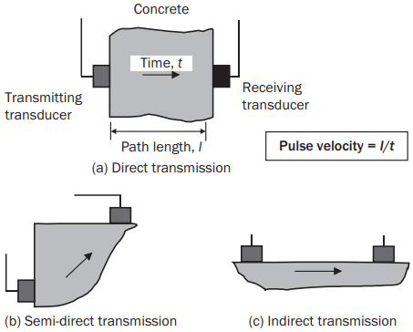
The ultrasonic signal is generated by a piezo-electric crystal housed in a transducer, which transforms an electric pulse into a mechanical wave. The pulse is detected by a second similar transducer, which converts it back to an electrical pulse, and the time taken to travel between the two transducers is measured and displayed by the instrumentation. Various test arrangements, illustrated in Fig. 3, are possible.
concrete.
Efficient acoustic coupling between the transducers and the concrete is essential, and is usually obtained by a thin layer of grease. The pulse velocity is independent of the pulse frequency, but for concrete fairly low frequencies in the range 20–150 kHz (most commonly 54 kHz) are used to give a strong signal that is capable of passing through several metres of concrete.
Transducers that produce longitudinal waves are normally used, although shear wave transducers are available. The velocity (V) of the longitudinal ultrasonic pulse depends on the material’s dynamic elastic modulus (Ed), Poisson’s ratio (v) and density (ρ):
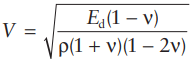
Hence the upv is related to the elastic properties of the concrete. As with Ed, it can be correlated empirically with strength, but with similar limitations of dependence on constituent materials and – as with the rebound hammer – moisture conditions, pulse velocity being up to 5% higher for the same concrete in a dry compared with a saturated state.
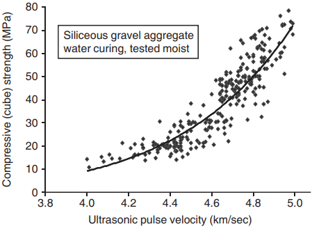
pulse velocity of concrete (UCL data).
Figure 4 shows UCL students’ data obtained on cubes tested in a moist condition. The relation is clearly nonlinear, which is to be expected since upv is related to the dynamic modulus, but shows a greater degree of scatter than the strength/Ed relationship in Fig. 7.
Two factors contribute to this; first the upv test requires a little more skill than the resonant frequency test, e.g. in ensuring good acoustic coupling between the transducer and the concrete. Second, the results were obtained on 100 mm cubes, and therefore a smaller and inherently more variable volume of concrete was being tested. Both these factors should be borne in mind when interpreting any non-destructive test data.
The ultrasonic pulse travels through both the hardened cement paste and the aggregate, hence the pulse velocity will depend on the velocity through each and their relative proportions. The velocity through normal-density aggregate is higher than that through paste, which leads to the broad relationships between between upv and strength for paste, mortar and concrete shown in Fig. 5.
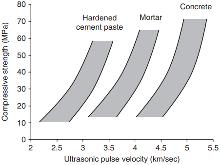
velocity for hardened cement paste, mortar and
concrete (based on Sturrup et al., 1984, and UCL
data).
The upv test has the great advantage of being able to assess concrete throughout the signal path, i.e. in the interior of the concrete. Direct transmission is preferred, but for in-situ measurements, semi-direct or indirect transmission can be used if access to opposite faces is limited (Fig. 3).
With in-situ testing, it is also very important to ensure that measurements are taken where they are not influenced by the presence of reinforcing steel, through which the pulse travels faster (upv = 5.9 km/sec), and which can therefore result in a falsely low transit time.
Resonant Frequency Test
This is a laboratory test on prepared specimens, and can be used to assess progressive changes in the specimen due, for example, to freeze–thaw damage or chemical attack, so it is therefore particularly useful for generating data in durability testing. It is covered by BS 1881-209.
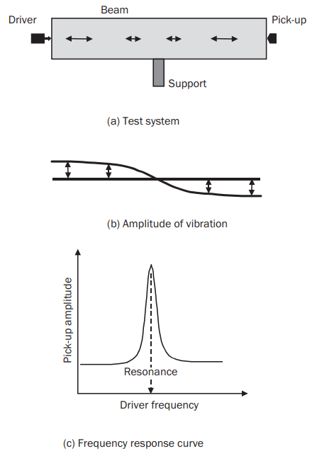
The specimen is in the form of beam, typically 500 × 100 × 100 mm; the test normally consists of measuring the beam’s fundamental longitudinal resonant frequency when it is supported at its midpoint.
A value of elastic modulus called the dynamic elastic modulus can be obtained from this frequency (n), the length of the beam (l) and its density (ρ) using the relationship:
Ed = 4.n2.l 2.ρ (23.2)
The resonant frequency is measured with the test arrangement shown in Fig. 6. The vibration is produced by a small oscillating driver in contact with one end of the beam, and the response of the beam is picked up by a similar device at the other end (Fig. 6a). The amplitude of vibration varies along the beam as in Fig. 6b. The frequency of the driver is altered until the maximum amplitude of vibration is detected by the pick-up, indicating resonance (Fig. 6c).
The frequency is normally displayed digitally and manually recorded. The test involves very small strains but, concrete is a non-linear material. The dynamic modulus, Ed, is therefore in effect the tangent modulus at the origin of the stress– strain curve, and it is higher than the static or secant modulus (Es) measured in a conventional stress–strain test.
The ratio of Es to Ed depends on several factors, including the compressive strength, but is normally between 0.8 and 0.85. As with the static modulus, for a particular set of constituent materials the dynamic modulus and strength can be related; Fig. 7 shows data obtained by students at UCL.
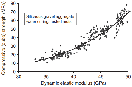
elastic modulus of concrete (UCL data).
The amount of scatter is less than that for rebound hammer vs. strength (Fig. 2), mainly because the dynamic modulus gives an average picture of the concrete throughout the beam, not just at a localised point.
The relationship is clearly nonlinear, as with those for static modulus and strength given in equations 20.13 and 20.14. The applicability of relationships such as those in Fig. 7 to only a restricted range of parameters (aggregate type, curing conditions etc.) must be emphasised.
It is also possible to set up the support and driver system to give torsional or flexural vibration of the beam, so that the dynamic shear or flexural modulus can be obtained.
Near-To-Surface Tests
The specific need to assess the strength of in-situ concrete has led to the development of a range of tests in which the surface zone is penetrated or fractured. Either the amount of penetration or the force required for the fracture is measured, and the strength estimated from previous calibrations.
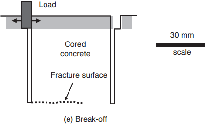
The limited amount of damage incurred does not significantly affect the structural performance of the concrete elements or members, but it does normally require making good after the test for aesthetic or durability requirements. There are five main types of test, illustrated in Fig. 8:
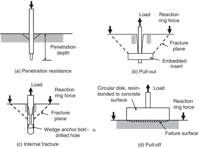
- In penetration resistance tests (Fig. 8a) a highstrength steel bolt or pin is fired into the concrete and the depth of penetration measured.
- In pull-out tests, the force needed to pull out a bolt or similar device from the concrete is measured. The device can either be cast into the concrete, as in Fig. 8b, which involves preplanning (although a version that fits into an under-reamed drilled hole has been developed) or be inserted into a drilled hole, as in Fig. 8c, with fracture being caused by the expansion of the wedge anchor. Their use in Europe is covered by BS EN 12504-3.
- In pull-off tests (Fig. 8d) a metal disk is resinbonded to the concrete surface and is pulled off; the failure at rupture is essentially tensile.
- Break-off tests (Fig. 8e) involve partial drilling of a core, and then applying a transverse force to cause fracture. The results have been shown to have a reasonable correlation with modulus of rupture strength.
There are a number of commercial versions of each test (Bungey et al., 2006). In each case, to give an estimate of compressive strength prior collaboration in the laboratory is necessary and, as with the truly non-destructive tests already described, considerable scatter is obtained, which must be taken into account when interpreting the results. Also all of the correlations – particularly for the aggregate type – are dependent on a number of factors.
Other Tests
Developments in instrumentation and increasingly sophisticated methods of analysis of the results have led to of a number of significant and useful methods of non-destructive testing. Some examples are:
- Maturity meters, in which a thermocouple is embedded in the concrete at casting and the temperature–time history recorded. This is particularly useful for estimating the early strength development of concrete.
- Radiography and radiometry. Gamma-ray imaging can show the location of reinforcing and pre-stressing rods and voids within the concrete, and the absorption of gamma rays can give an estimation of density.
- Impact-echo and pulse-echo techniques, in which the response of the concrete to an impact on its surface is measured, by for example a geophone or an accelerometer. Voids beneath slabs or behind walls can be detected, and the pulse-echo technique in particular is useful for integrity testing of concrete piles.
- Acoustic emission, which can detect the sounds produced by concrete cracking. This is mainly suitable for laboratory use.
- Radar systems, in which the reflections and refractions of radar waves generated by a transmitter on the surface of the concrete can be interpreted to give an evaluation of the properties and geometry of subsurface features.
With the exception of maturity meters, most of these require considerable expertise in carrying out the tests and interpreting the results, which is best left to specialists. Bungey et al. (2006) provide a useful account and comparison of these and other methods.
Finally, in many cases of structural investigation, a direct measurement of compressive strength is often required, and so cores are drilled which are tested after appropriate preparation.
This is costly and time-consuming, and is best carried only after as much information as possible has been obtained from non-destructive tests; a combination of tests is often used to give better estimates of properties than are possible from a single test.
Thanks for reading about “non-destructive testing of concrete”.