FRC Reinforcement Layouts
The manner in which fibres are distributed throughout an FRC component is determined largely by the manufacturing method. As with FRP, choosing the correct fibre layout or fibre architecture for a given loading case is crucial in order that the fibre can be used most efficiently. There are two key parameters: fibre length and fibre orientation.
As an FRC component is loaded, an embedded fibre can ‘fail’ in one of two ways; either it can break in two, or it can be pulled out of the cement or concrete matrix. Either mode of failure may be desirable, depending on the particular FRC application. There is a critical length of fibre, lc, which is the minimum length of fibre required such that on failure of the matrix, the full strength of the fibre is mobilised (i.e. the fibre will break rather than pull out of the matrix, as illustrated in Fig. 47.1).
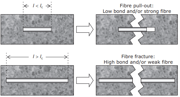
At the critical length:

where σfu = ultimate strength of the fibres, Af = cross-sectional area of the fibre, Pf = bond area and τ = bond shear strength.
For a cylindrical fibre, Af/Pf = r/2 where r is the radius of the fibre. We therefore see that the critical length decreases with increased bond strength and increases with increased fibre strength. Fibre length l is expressed in terms of critical length lc when analysing FRC behaviour.
The threshold for longfibre behaviour is ~5 lc, but in practical terms the difference is usually between effectively continuous fibres and short chopped fibres. This change in mode of failure is critically important to FRC designers, who need to select the correct mode of failure (or combination of modes) for a given application by careful specification of fibre type, fibre length and bond parameters. Critical length is much lower in multifilament/microfibre FRC compared with macrofibre FRC.
Typical calculated values for plain, uncrimped steel fibres and glass strands would be 100 mm and 7 mm, respectively (which is why almost all steel fibres used for modern FRC have crimped profiles and/or hooked ends to decrease the effective value of lc). Fibre orientation can be 1-dimensional (i.e. aligned fibres), random 2-dimensional (normally in thin sheets, random in plan view but aligned when viewed edge-on) or random 3-dimensional (dispersed throughout a bulk concrete), as illustrated in Fig. 2.
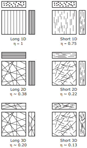
Aligned layouts allow fibres to be placed parallel to the applied stress, optimising reinforcement efficiency at the expense of creating anisotropic properties (a ‘grain’ effect, as in timber). Random layouts give uniform properties in all directions at the expense of peak strength or toughness. Combinations of layouts can be used to give intermediate behaviour.
Efficiency factors
Efficiency factors (0 ≤ ɳ ≤ 1) are used in analysis to account for this variation in composite properties with fibre architecture. For a given architecture, ɳ will be a function of l, lc and the fibre orientation. For long (i.e. continuous) fibres aligned in the direction of applied stress ɳ = 1, i.e. the fibres are fully mobilised.
However, this is a very unusual layout and for most applications ɳ < 1 and must be calculated. There are various analytical approaches to determining ɳ, derived from statistical considerations of fibres crossing cracks within an FRC, but most return similar values. Three scenarios are of interest. For short, aligned fibres (Bentur and Mindess, 2007, p. 109):
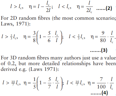
We can use these factors to define an effective volume fraction Vf′ = ɳVf . It is useful to think of this as the volume fraction of fibres in the composite that are aligned with the direction of applied stress. Typical efficiency factors (for l = 2lc where relevant) are included in Fig. 2 for each layout.
For example, using a 3D short-fibre layout would require three times more fibre to achieve the same effective volume fraction (and hence FRC properties) as using a 2D long-fibre layout.
Textile reinforcement
In order to provide better control over the fibre architecture, engineered textiles are increasingly being used. In primary FRC applications where significant continuous structural loads are to be carried, textiles allow the reinforcement to be placed to optimise load resistance for a given Vf , rather than be equally distributed throughout the cross-section, as with simple FRCs. By varying Vf throughout the thickness, resistance to bending can also be increased (e.g. by concentrating textile on the tension side of the neutral axis). Most FRC textile is made from glass fibres, although carbon, aramid and hybrid textiles containing mixed fibre, often including polymers, are also available.
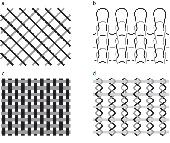
There is a huge variety of textile forms available, but for FRC purposes the textiles must have a relatively open structure (to permit ingress of the cementitious matrix) and displacement stability (to prevent distortion during composite manufacture). Such textiles fall into three categories, illustrated in Fig. 47.3:
- scrim, a ‘loose’ bi- or multi-axial textile, in which superimposed threads are not fixed at the crossing points (Fig. 47.3a)
- warp knits, in which crossing threads are knotted and/or looped to provide stability (Fig. 47.3b)
- weave, a ‘tight’ bi-axial textile with two orthogonal thread systems – the warp and weft – that cross alternately (Fig. 47.3c,d).
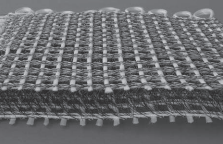
Combinations of basic forms can also be made. Modern textiles can be produced in multiple layers interlinked with binding or spacer warp thread to produce 3D reinforcement architectures such as tubes or sandwich structures (Fig. 4). The efficiency factors applicable to simple textiles can easily be estimated (e.g. for the simple scrim in Fig. 47.3a it would be 0.5) but for more complex textiles experimental values would need to be obtained.