Definition: The behavior of materials under fluctuating and reversing loads (or stresses) is known as fatigue. This behavior is different from that under the steady load.
Fatigue is, however, not a dynamic effect. The rate of loading is usually not a factor in fatigue behavior. Fatigue behavior is experienced by all materials whether metals, plastics, concretes, or composites.
Effects of Fatigue in Materials
The main effects of fatigue on the properties of materials are the following.
- Loss of ductility,
- Loss of strength, and
- Enhanced uncertainty in strength and the service life of materials.
Salient features
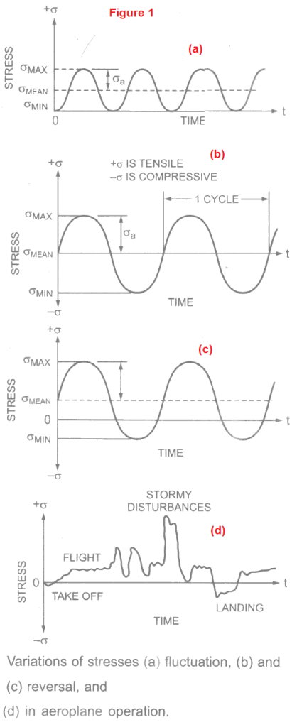
Fatigue occurs at stresses well within the elastic range. Various types of fluctuating and reversing stresses are shown in Figure 1.

In practical situations, the stress variations may be drastic, unpredictable and complex. One such example, Figure 1(d), is that of an airplane during its take-off, flight and landing.
- In these diagrams, the range of stresses vary from a maximum σmax in tension to a minimum σmin which may be in compression or tension.
- The mean stress σmean remains constant but the stress amplitude as fluctuates as the number of cycles N increases.
- These stress parameters may be caused due to oscillations under axial loading, bending, torsional loading and combined loadings.
Fatigue Limit and S-N Diagram
Total number of cycles N required to bring about fracture in a material (or its specimen) under an applied stress defines its basic fatigue life. Fatigue life of a material is expressed in percent survival out of large number of specimens.
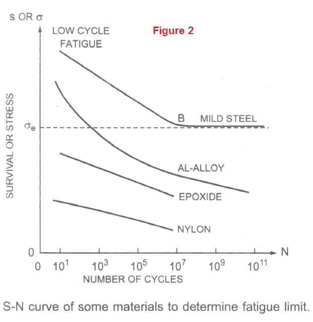
Generally median fatigue life is estimated at 50% survival. It is evaluated from the data of stress (S or σ) and number of cycles of failure N by conducting fatigue test. The plot is referred to as S-N diagram. The S-N curves for some materials are shown in Figure 2.

The curve of mild steel is asymptotic beyond B. It implies that the material can withstand a stress equal to σe, for any number of cycles without fatigue fracture. This stress is called as endurance stress. It is also known as fatigue limit.
This stress is generally 0.3 to 0.5 times the ultimate strength of materials. Ferrous metals usually have a fatigue limit but non-ferrous metals and non-metals often do not. It may be seen in above figure for aluminium alloy, epoxide and nylon. Design engineers are mainly concerned about endurance stress of materials in specific applications.
Critical Applications of Fatigue Behavior
The consideration of fatigue behavior is very important and critical in the following applications.
- Wings of airplanes and other aircrafts.
- Leaf springs used on automobiles and railways rolling stocks.
- Connecting rods of internal combustion engines.
- Rotating shafts and machine parts.
- Rubber tyres etc.
It will not be out of place to mention that many of the airplane accidents are caused due to fatigue failure. Crashing of Boeing-747 in June 1986 at Narota airport in Tokyo, Japan is one among such examples.
Mechanism of Fatigue Fracture
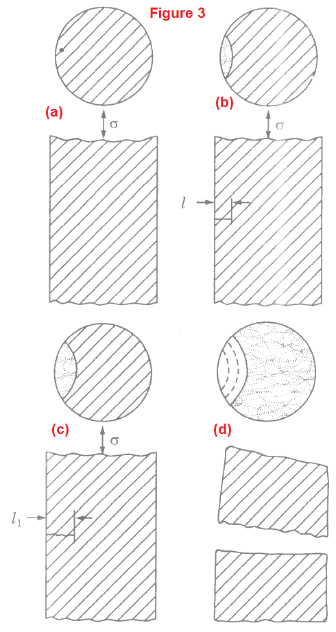
Fatigue fracture involves following steps during fatigue loading. These steps are shown in Figure 3 (a – d) in sequential order.

- Nucleation of crack Figure 3(a),
- Crack growth Figure 3(b),
- Crack growing to a tiny size Figure 3(c), and
- Fracture Figure 3(d).
Nucleation is attributed to brittle particles, discontinuities; stress raisers such as flaws, sharp corners, holes, keyways and fillets. Flaws may be in the form of blowholes, inclusions and fabricational defect cracks. Nucleation is caused when the maximum stress σmax within the elastic range fluctuates or alternates from tensile to compressive.
With continued load cycles, the cracks grow to microscopic size and gradually become visible to the eyes. Fracture occurs when cracks reach to some critical sizes, thereby resulting in reduced effective cross-sectional area of the material.
Types of Fatigue Fracture
Fatigue fracture can be distinguished in the following categories.
1. Fatigue of cracked components
Cause: Pre-existing cracks
Examples: Pressure vessels, ships, bridges and other structures containing welds.
2. Fatigue of un-cracked components
Cause: Initiation of cracks
Examples: Gear teeth, crankshafts, ball bearing races, piston pins and other small components.
(a) Low Cycle Fatigue
Cause: Failure at stresses above yield strength at <=104 cycles.
Examples: Parts of steam turbine, nuclear reactor core, and other components subjected to occasional overloads.
(b) High Cycle Fatigue
Cause: Failure at stresses below yield strength at 104 cycles.
Examples: Rotating wheels, axles and engine components, and other vibrating systems.
Improving the Fatigue Life
Several methods are adopted to improve the fatigue life of machine and structural components. Following are the main methods used in this regard.
- Stress raisers such as sharp corners are avoided so that the stress concentrations vanish or diminish considerably.
- Materials with finer grain sizes are utilized.
- Surface irregularities and cracks are removed by polishing the surfaces. 4. Compressive stresses are introduced at the surfaces by processes such as shot peening, shot or sand blasting etc.
- Nitriding and carburizing operations are performed to create strong surface layers.
Fatigue Test
We have discussed the fatigue behavior and its effects so far. We have noticed that the fatigue failure is characterized by its endurance stress i.e. fatigue limit. Here, we shall concentrate on the fatigue testing and experimental determination of the fatigue limit.
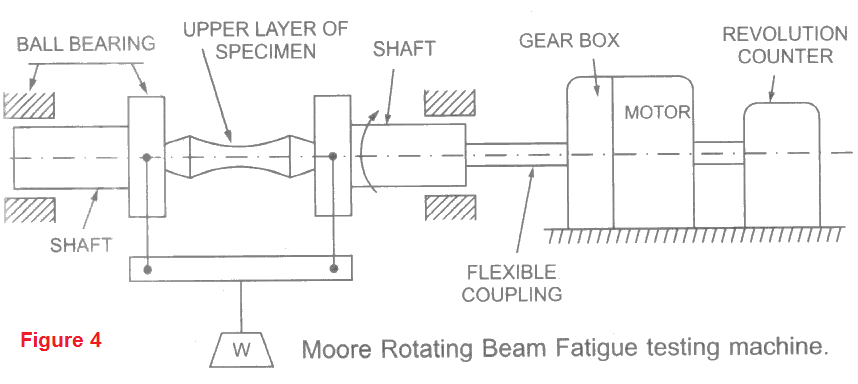
Construction of test set-up: The fatigue limit of a material is determined on a Rotating Beam Fatigue Testing Machine as shown in Figure. A polished specimen (beam) is placed as simply supported beam and loaded in pure bending by a dead weight W.

The beam rotates in the ball bearings at speeds ranging between 3000 to 10000 RPM. A variable speed motor or a constant speed motor with a gear box is used for this purpose. The topmost layer of the rotating beam specimen always remains in compression while the bottommost in tension. Thus a sinusoidal alternating stress is produced on the surface of the specimen during each rotation.
A mechanical revolution counter records the number of cycles of stress reversal. The machine goes-off when the specimen breaks.
Statistical Nature of Fatigue Test
The fatigue test is of statistical nature. A population of specimen (say 100 specimens) is tested at varying maximum stress σmax, mean stress σm, alternation stress σa and stress ratio ((σmin/σmin). The frequency curves and histogram are plotted. The central tendency and deviations are obtained.
Normally a median curve between survival S (stress σ) and number of cycles N is plotted and endurance stress σe, may be evaluated from them.