Durability of FRC
Combining a continuously hydrating, highly alkaline matrix with a wide variety of types, shapes and sizes of reinforcing fibres will lead to complex, time-dependent fibre–matrix interactions. These interactions lead to the engineering properties of most FRC varying markedly with time. This was recognised by even the earliest modern FRC researchers, so the durability of FRC has been extensively studied for several decades.
A good deal more is probably known about the mechanisms and magnitudes of FRC durability issues than those of any other composite material. It is important that the FRC designer is aware of these issues from the outset to avoid unwarranted failures in FRC components.
TIME-DEPENDENT BEHAVIOUR
Multifilament/microfibre FRC

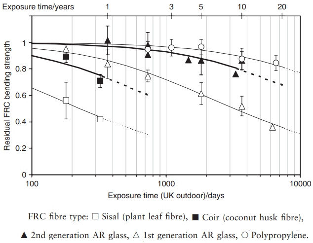
In Fig. 1, the residual bending strength for various common types of multifilament, PC matrix– FRC is plotted as a function of time of exposure to UK outdoor weathering conditions. The strength is expressed as a fraction of the original, as-supplied value. The fibres in each case are intended to provide primary reinforcement. The main observations to note are:
- There are appreciable losses in strength with time for most FRC types, and these need to be accounted for in design.
- The magnitude of the strength loss is very different not only between different fibre types, e.g. polymer compared to natural fibres, but also within different fibre types, e.g. coir compared to sisal and 1st compared to 2nd generation AR glass. Thus we cannot talk about overall FRC durability; it varies according to the particular composite being used.
- In terms of durability, we can rank the various fibre types as polypropylene > 2nd generation (i.e. modern) AR glass >> 1st generation AR glass >> unprocessed natural fibres (Purnell, 2007).
Primary FRC will degrade until the composite strength is reduced to the matrix strength, at which point all region II and III behaviour will be lost. In secondary FRC, we have seen that the benefit provided by the fibres – region IV toughness – is not related to the composite strength, which is generally less than the matrix strength.
In fact, as the composite ages, the matrix tends to increase in strength. This can give misleading results. For example, the strength of some cellulose-fibre secondary FRC can increase by half over five years of exposure as the matrix hydrates, increasing matrix strength and bonding. Yet the strain to failure (an indicator of region IV performance) over this period decreases from 3% to < 0.1% (Akers and Studinka, 1989).
Thus in many cases, it is more appropriate to monitor toughness or strain to failure instead of strength in durability studies. However, since there is no accepted standard toughness test for FRC, and strain-to-failure results often have large scatter, strength remains the most popular metric. There is not much information available on FRC made with fibres other than those shown in Fig. 1. Studies on PVA–FRC report no strength loss after about 7 years of weathering, but since Vf is almost always less than Vfcrit this does not necessarily prove its durability. No long-term weathering studies of carbon–FRC have been reported. Carbon fibres are generally assumed to be inert and immune to any corrosion-related strength loss, but it is possible that other mechanisms (see below) could affect their long-term properties.
Monofilament/macrofibre
FRC Time-dependent behaviour in steel–FRC has been less extensively studied. Its performance is more frequently compared with that of traditional RC, so attention has tended to focus on RC-related issues such as surface spalling, cracking and structural integrity rather than directly measuring strength loss. Even after several months of the most severe lab-based environments (cyclic wetting/drying in hot saline solutions), steel–FRC retains 70% of its strength and 40% of its toughness (Kosa and Naaman, 1990). In normal service only superficial corrosion of fibres at the surface is to be expected unless significant structural cracking is present (in which case, the engineer generally has more pressing concerns). Other monofilament/macrofibre FRCs are not common enough for durability data to have been reported.
PROPERTY LOSS MECHANISMS
There are two types of process that can cause loss of mechanical properties in FRC: weakening of the fibre and processes associated with the progressive hydration and development of the cementitious matrix. Both types can reduce the strength of primary FRC, change the failure mode of FRC from primary to secondary by eliminating region II/III behaviour, or reduce the toughness of secondary FRC (i.e. reduce WIV). The severity and relative importance of each type will be different for each FRC, and affected by fibre type, matrix chemistry, Vf and intended composite action.
Fibre weakening
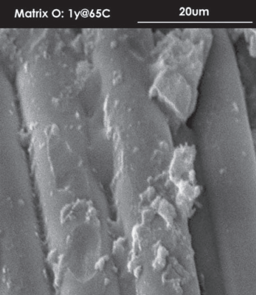
Most cement-based matrices are highly alkaline, the pore water having a pH of 12–13. Many fibres can degrade in these environments. Cellulose, common glass (E-glass) and some polymer fibres may suffer gross corrosion, i.e. the effective cross-sectional area of the fibres is significantly reduced (Fig. 2).

Alkali-resistant (AR) glass fibres do not suffer gross corrosion in normal service, but sub-microscopic flaws form, which act as Griffiths stress concentrations; these grow, slowly weakening the fibre. Steel fibres are of course passivated (covered with a tightly adhering molecular layer of protective oxide;) in these alkaline conditions in the same way as reinforcing bars in normal reinforced concrete.
They will only corrode if that passivation is disrupted by carbonation or chloride ions. Natural fibres also tend to weaken as they absorb water from the surroundings. Reduction of fibre strength contributes to four mechanisms for loss of durability:
- In primary FRC, it reduces the composite strength since σcu is proportional to σfu.
- Since Vfcrit is inversely proportional to σfu then a loss of fibre strength increases the critical volume fraction. If Vf is not sufficiently high to accommodate this, the failure mode can change from primary to secondary by eliminating the multiple cracking and post-cracking behaviour . This is often of greater concern than simple strength reduction since it is accompanied by a drastic loss of toughness, especially if l >> lc.
- In secondary FRC, a reduction in sfu reduces the upper bound for region IV and thus potentially WIV.
- It also leads to a reduction in the critical length lc. This increases the likelihood that the dominant failure mode in secondary FRC will be fibre fracture rather than fibre pull-out, significantly reducing the toughness of the composite (i.e. WIV), will be significantly reduced or eliminated).
Continued matrix hydration
In common with most pre-cast cementitious products, FRC is generally supplied or installed after having been cured for periods ranging from about 7 to 28 days. A significant proportion of unhydrated cement will remain available for hydration at this time and its continued hydration can cause a number of durability issues.
The critical fibre volume fraction is proportional to the matrix strength. If the matrix strength increases sufficiently after installation (increases of 10–30% are typical) and if Vfcrit was borderline to start with, then the failure mode may change from primary to secondary with a corresponding loss of toughness. The initial interface between the fibres and the matrix tends to be quite ‘loose’ and porous.
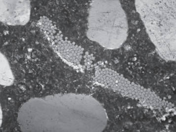
The matrix at the interface is relatively weak and the bond strength is low. As the matrix hydrates, this interface becomes denser, and in multifilament FRC the spaces within the fibre bundles may also become partially filled with various hydration products, particularly calcium hydroxide crystals (Fig. 3).

The direct effect of this densification is to significantly increase the bond strength, perhaps by a factor of up to 3 (Purnell et al., 2000). Increased bond strength τ is generally welcomed in most composites as it increases the efficiency of the fibres. In secondary FRC, though, since increased bond strength also decreases the critical length it may decrease the toughness, WIV, in the same manner, by changing the fibre failure mode from pull-out to fracture. Indirect effects of interfacial densification may include:

- Localised aggravation of fibre degradation – ‘notching’ – by calcium hydroxide crystals growing at the fibre–matrix interface, which can weaken fibres.
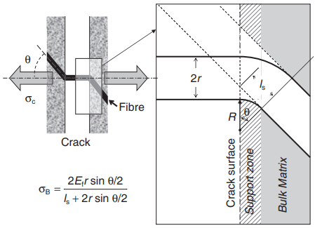
- Loss of flexibility of multifilament strands as the spaces between the filaments are filled with hydration products. Strands bridging cracks rarely do so at right angles and thus have to be able to bend freely (Fig. 4). This also affects natural fibres in a process known as mineralisation, where the lumens within the fibres become filled with calcium hydroxide precipitates, causing similar effects.
- Decreased radii of curvature – and thus increased bending stress σb – in monofilament fibres crossing cracks, as the ‘support zone’ becomes stronger and less able to yield locally under a fibre (see Fig. 4).
- Decreased contrast in fracture toughness, KIC, between the interface and the bulk matrix, which prevents the ‘crack blunting’ mechanism .
DESIGNING DURABLE FRC
There are three approaches to designing durable FRC and the approach, or combination of approaches, to be taken in any given case will depend on the fibre type, installed application and commercial considerations.
Good design and manufacturing practice
The most important approach is to encourage high quality with regard to FRC manufacture. It is good practice to specify a mean fibre volume fraction to be used that is somewhat in excess of that indicated by design calculations. This will give some protection against many of the mechanisms outlined above.
It is important to then apply a sensible factor of safety to this value, and to carefully monitor quality control during manufacture both to ensure that the volume fraction remains high and that the fibres are placed and consolidated properly to maximise their efficiency.
‘Skimping’ on fibre content to save a few pennies at the manufacture stage can have expensive (and possibly litigious) consequences in the longer term. Good practice with regard to the matrix – good compaction, high cement contents, low water:cement ratio etc. – will also protect against ingress of outside agents (chlorides, water) that can damage e.g. natural or steel fibres.
Increasing fibre resistance
Making fibres less susceptible to attack by the matrix will increase durability. For example, virtually all glass fibres now used in FRC are ‘secondgeneration’ fibres, which combine alkali-resistant glass with a soluble coating that reduces the precipitation of calcium hydroxide crystals at the interface.
In very demanding environments (e.g. marine structures), galvanised or alloy steel fibres may be used to help prevent corrosion of the steel. Multifilaments such as natural fibres may be treated in various ways to increase their alkali resistance, often by pre-impregnation with fine materials such as microsilica, or polymers, which block calcium hydroxide precipitation. Carbon and polypropylene fibres are generally assumed to be more-or-less inert and so other approaches are required.
Matrix modification
Another approach is to modify the matrix so that it is less aggressive towards the fibres. This can be achieved by reducing the alkalinity of the matrix, and/or its propensity to precipitate calcium hydroxide at the interface. Additions are invaluable in this respect, since they react with both the free alkali and the calcium hydroxide in the matrix.
Waste materials such as microsilica, blastfurnace slag or fly ash, plus manufactured materials such as metakaolin (a calcined china clay) are all routinely used in most multifilament FRC where durability is a prime concern, and can significantly increase the predicted service life of the materials, especially in warm service conditions (e.g. Purnell and Beddows, 2005).
Additions are also added to steel–FRC matrices to provide the same durability benefits as in reinforced and pre-stressed concrete, i.e. increased resistance to carbonation, ingress of chloride, and penetration of water.
In glass–FRC, the matrix is frequently modified by adding acrylic polymer dispersions. As well as acting as a curing and workability aid, these polymers enhance durability, reducing the degree to which strainto-failure is degraded over about 20 years by 75% (Ball, 2003).
The mechanism by which it works is not clear, but it probably involves disrupting the precipitation of calcium hydroxide at the interface rather than providing a protective coating on the fibres. An alternative approach is to use non-Portland cement systems such as calcium aluminate cement or sulpho-aluminate cements, which have lower intrinsic alkalinity and develop little or no calcium hydroxide during hydration.
This is in its infancy but some such matrix formulations are commercially available, especially in China. Such matrices often have other advantages such as lower embodied energy/CO2 and rapid strength development, which will see them being used more widely in the future.
MODELLING AND SERVICE LIFE PREDICTION
Predicting strength loss in FRC is important, as it is the most widely used property in specifying the performance of the material. Several models of the strength vs. time relationship have been proposed, mainly for glass–FRC, that take into account one or more of the various parameters that affect the service life (e.g. service temperature and humidity, matrix chemistry and hydration, fibre type and so on). The most recent relates normalised strength S (i.e. the ratio of the strength at a given time to the original strength) to time (t) using a relationship of the form:

The parameter n is normally taken as either 1 or 0.5 depending on the assumptions made, but 0.5 is probably the more correct value. The rate constant k depends on the service temperature, the particular fibre/matrix combination concerned, and the value of n used. Table 1 gives some typical values of k for glass–FRC. Using this relationship, a critical normalised strength can be defined (usually the original value of σc,A/σcu, i.e. the threshold at which region II/III toughness is lost) and service lifetimes predicted. Values of 60 and 80 years for PC-matrix and modified matrix glass–FRC have been suggested (Purnell, 2007).

RECYCLING
Recycling of any composite component in an assembly involves one of three options:
- disassembly and consequent reuse of entire components in a new structure or other application
- reduction of the composite into its component phases (i.e. fibre and matrix) and separate recycling of each phase
- crushing and recycling of the composite component as a lower-grade material.
When considering FRC, all these options are problematic. Recycling of entire components is the most promising option, but is rarely carried out. FRC panels tend to be used in external applications, and in common with all other types of external panel, are subjected to more weathering than other structural components. Thus it is unlikely in general that they will outlast the rest of the structure.
Reduction of FRC into fibre and matrix is neither economically nor technically feasible. Chemical separation processes involving dissolution of the matrix would most likely damage the fibre and produce large quantities of waste. Physical separation is not possible, except conceivably for some steel–FRC.
Regulations surrounding the use of crushed and recycled construction materials (i.e. BS8500-2) as aggregate limit the content of ‘other foreign material’ such as glass or plastics to < 1.0% by mass, and the mass fraction of ‘fines’ (i.e. particles passing the 0.063-mm sieve) must be less than 5%. The high fibre and cement content of most primary FRC, plus the possibility of microfibres passing the sieve, will exclude it from being recycled in this way.
However, some secondary FRC with suitably low Vf may be able to be recycled as either aggregate for structural concrete, i.e. as recycled concrete aggregate (RCA), or for low-grade concrete, structural sub-base for roads or to make-up ground level, i.e. as recycled aggregate, RA.