Component Materials of FRC
FIBRE
Almost every imaginable type of fibre has been used at some time or another with cement or concrete. The most commercially significant types are described below and their properties are summarised in Table 1. Here we focus on the properties particularly relevant to FRC.
Polymer fibres
Polymer fibres have been used very successfully in FRC for many years. Since the modulus of elasticity of polymers tends to be rather less than that of the matrix (~5 GPa vs. ~20 GPa) they normally only provide a secondary or tertiary reinforcement action (providing ‘post-peak’ strength and toughness, or controlling shrinkage cracking) unless quite high values of Vf > 5% are used.
Polypropylene (PP) fibres are the most commonly used polymer fibre for FRC and are made by extruding high-molecular-weight PP into either monofilaments or films. These are then stretched in order to orient the polymer molecules, which improves the fibre modulus from around 2 GPa to > 5 GPa. Short monofilaments are used at low Vf (as tertiary reinforcement.
Films are ‘fibrillated’ , with tape-like cross-sections of effective diameter ~0.05 to 0.5 mm and used as secondary (0.5% < Vf < 5%) or more rarely primary (Vf > 5%) microfilament reinforcement in thin sheet FRC. Since the PP fibre surface is chemically hydrophobic, it is normally treated in some way in order that a reasonable bond with cement paste can be formed. The use of other polymer fibres in FRC is much less common.
Acrylic and polyester fibres are not stable in the high pH environment of most cementbased matrices and are thus not suitable for FRC. There is some interest in using nylon fibres as a replacement for PP but commercial use is not widespread.
Polyethylene fibres have been used as short dispersed fibres in concrete (Vf ~4%) and in fibrillated ‘pulp’ form as a direct replacement for asbestos fibre (Vf ~10%). Their slightly higher modulus compared with that of PP (5–30 GPa depending on processing) and improved mechanical bond with the cement matrix mean that they have greater potential to produce primary FRC than PP. Certain polyvinyl alcohol (PVA) fibres are also suitable to act as asbestos replacement in FRC.
They have relatively high modulus and strength (20–30 GPa and 1200–1500 MPa, respectively) and bond chemically to the cement matrix, so at Vf = 3% they can provide a significant primary reinforcement action. Aramid fibres – such as Kevlar® – are special polymer fibres with aligned chain microstructures, imparting much higher mechanical properties than other polymers (moduli of ~70–120 GPa and tensile strengths of ~3000 MPa).
The unit ‘fibre’ is actually a bundle (called a tow or roving) of several hundred filaments, 0.010–0.015 mm in diameter. The price of these high-performance fibres is currently too high for serious commercial FRC application but they could potentially provide very effective primary reinforcement.
Steel fibres
Historically, the use of steel–FRC has probably outweighed that of any other FRC; it is still very widely used, although polymer–FRC is catching up fast. In all cases, steel fibres can only provide secondary or tertiary monofilament reinforcement, since workability issues prevent Vf from exceeding 1.5–2% and the fibres are normally dispersed in a random 3D manner throughout the concrete matrix, which minimises their reinforcement efficiency.
Fibres for general use are made from ordinary carbon steel, although where enhanced corrosion resistance is required (e.g. marine applications) stainless alloy steel or galvanised fibres may be used. There are many manufacturing routes, including simple wire drawing, melt spinning or manufacture from cut sheet steel.
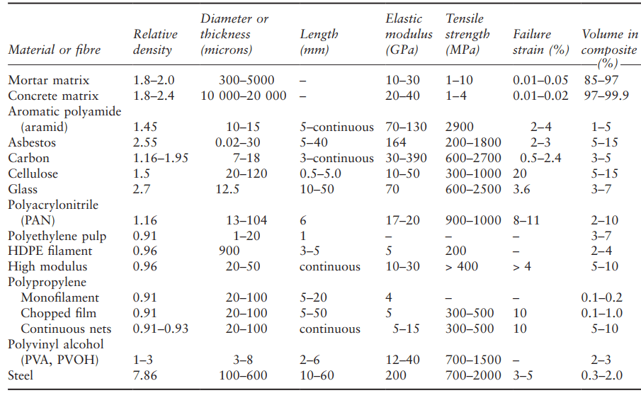
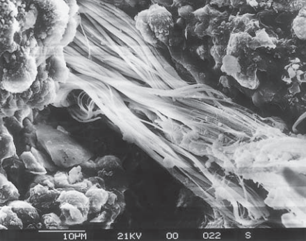
This leads to a variation in tensile strength from around 350 MPa to > 1000 MPa, although the modulus remains constant at about 200 GPa. All modern steel fibres intended for use with FRC have complex cross sections (e.g. crimped, twisted or flattened) and/or deformed axial shape (e.g. hooked ends or a ‘wavy’ shape) to maximise the anchorage between the fibre and the matrix (Fig. 1).
mechanical deformation.
Physical and chemical surface treatments may also be applied to enhance the bond. Equivalent diameters and lengths vary from 0.1 to 1 mm and 10 to 60 mm, respectively.
Natural fibres
Natural fibres – by which we generally mean those of vegetable origin – are the oldest form of reinforcement for cementitious materials.
The motivation for use of a particular natural fibre normally stems from the desire to use a cheap, locally available and sustainable resource. Technical performance issues are of secondary interest, since the use of most viable natural fibres will lead to similar FRC properties, i.e. inferior to those of glass-, steel- or polymer-FRC.
Since the fibres also have a poor tolerance for the highly alkaline FRC matrix, they also degrade quickly. However, since natural fibres are normally used to provide tertiary reinforcement, permitting easier shaping of green forms, or short-term secondary toughness to permit installation handling, their use is widespread, particular in less economically developed countries. The volume fraction rarely rises above 5% except in specialised cases where a natural fibre is used as a direct replacement for asbestos in the Hatschek process.
Fibres derived from plant stems (e.g. jute and flax), leaves (e.g. sisal), or woody parts (waste structural wood or bamboo) are processed to extract the cellulose-rich fibres from the organic matrices. The degree of processing applied will determine the quality of the fibres; jute, flax and sisal are relatively easily processed using natural methods called ‘retting’ to produce medium-quality fibres.
To extract fibres from timber, it must be chipped and heated in industrial processing plants, but high-quality cellulose fibres can be obtained. Other fibres such as cotton and coir (coconut husk) can be extracted with minimal processing, but tend to be of low quality.
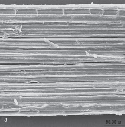
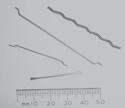
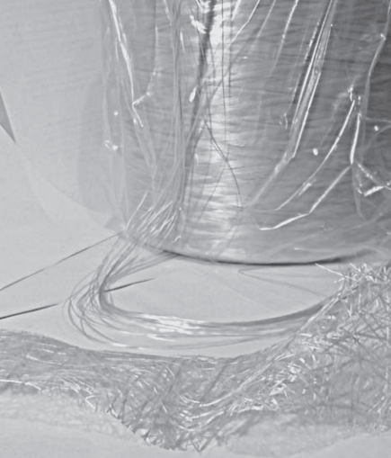
However obtained, all natural fibres have the same basic multifilament structure (Fig. 2a). A single fibre is effectively a roving, with a variable number of strands of ~100 cellular filaments. Each of these cells is a tube, around 1–2 mm long and < 50 mm across, with a hollow central core called a lumen. The walls of the tube are a composite of crystalline cellulose fibres in a hemi-cellulose–lignin matrix (Fig. 2b); the roving itself is held together by more lignin. The lumen has a tendency to absorb water, and the fibre properties are strongly dependent on the water content.
As the degree of processing increases, the roving is progressively separated into strands, removing the low-strength lignin and concentrating the high-strength cellulose fibres. The properties are highly variable; strength and stiffness may range from 200 to 800 MPa and 10 to 80 GPa, respectively, depending on fibre type, quality and processing parameters.
Glass
As with polymer matrices, glass fibres are frequently used to reinforce cement composites. Standard ‘E’ glass (from the SiO2–CaO–Al2O3–B2O3 system) is not stable in most cement-based matrices owing to their highly alkaline nature, so special alkali-resistant (AR) glass fibres (SiO2–Al2O3–ZrO2–alkali oxide) are used in commercial glass–FRC.
The addition of zirconia reduces (but does not completely halt) the overall rate of reaction between the glass and the alkaline matrix and also causes a protective zirconiarich layer to form on the fibre surface. Since the modulus and strength of the glass are around 70 GPa and 1500 MPa, respectively, it can be used to manufacture primary FRC; in fact, glass–FRC is probably the most common primary FRC, generally formed in thin sheets by spraying, with Vf ~5%. It is also sometimes used as secondary and/or tertiary reinforcement in larger concrete components. It is always used in multifilament mode.
strand mat. Background – continuous roving for
chopping.
Glass fibres are normally supplied as rovings of up to 64 strands, each with ~200 filaments of ~14 mm diameter. They may be supplied as a continuous roving on a roll and chopped to length of 10–40 mm during primary FRC manufacture, or come prechopped to 3–15 mm for secondary/tertiary applications (Fig. 3).
The strands are held together by a size (typically based on polyhydroxyphenol), which modifies the hydration of the matrix at the interface to help promote durability. Although the strain to failure is relatively low (~2%), this is significantly more than that of the cement matrix, so very useful toughness can also be provided by glass fibres.
Carbon
Carbon fibres were commercially developed in the USA in the 1960s. Their very high strength- and stiffness-to-weight ratios quickly found them applications in high-performance polymer composites and, as with most fibres, it was only a matter of time before they were investigated for use with FRC. As their price falls, they are becoming increasingly attractive and several commercial carbon–FRC applications have now emerged.
They are particularly attractive for FRC since the carbon is virtually inert with respect to the alkaline environment in the cementitious matrix. A single carbon fibre naturally forms a tow of around 10 000 filaments, each about 7–15 mm in diameter. The filaments consist of stacked layers of graphite, oriented more-or-less parallel with the fibre axis. Within the layers strong covalent bonds prevail, while the layers are held together by weak van der Waals bonding.
for FRC.
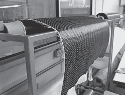
The strength of the fibre varies depending on the manufacturing method; as the degree of distortion of the layers decreases and thus a greater proportion of the layers are oriented parallel to the fibre axis, the strength increases. Pitch-based fibres (modulus ~30 GPa and strength ~600 MPa) are normally used for FRC, as they are rather cheaper than the polyacrylonitrilebased fibres, which are about 10 times stiffer and 4 times stronger. The fibres can be formed into a convenient fabric for use in FRC (Fig. 4).
Asbestos
Although the use of asbestos–FRC is now banned in most developed countries, it is still very commonly encountered during refurbishment of older buildings so a brief description is appropriate here. Asbestos fibres are derived from naturally occurring crystalline fibrous silicate minerals. The two most commonly encountered are white asbestos (chrysotile, a serpentine mineral) and blue asbestos (crocidolite, an amphibole mineral). Both have a microstructure based on silicate sheets; a planar banded structure interspersed with iron and sodium compounds in blue asbestos, and a ‘roll of carpet’ structure interspersed with brucite (Mg(OH)2) in white asbestos.
natural weathering for more than 10 years.
These chemical structures are highly stable in the alkaline cement environment, and their surface chemistry and particle size/shape allows a stiff, felt-like slurry of asbestos fibres and cement to be produced in an automated, continuous process, resulting in a final hardened thin sheet product with Vf ~10% (Fig. 5).
Fibre diameters are typically 20–200 nm (i.e. 2–3 orders of magnitude smaller than glass or carbon, hence the damaging bioactivity). The length varies with the processing method but rarely exceeds 20 mm. The strength and stiffness of such small fibres is very difficult to measure so reported values vary widely, but values of 1000– 2000 MPa and 160 GPa, respectively, are typical.
MATRICES
There are a wide variety of matrices for FRC. At one end of the scale (tertiary FRC), fibres are simply added to a standard concrete in order, for example, to control plastic shrinkage. At the other extreme (primary FRC), a cementitious matrix may be specially developed for use with a particular type of FRC, with mix design, admixtures and additives chosen to optimise e.g. textile penetration, composite durability, manufacturability and/or surface finish.
However, the majority of these matrices are based on Portland cement (though frequently heavily modified), is only aspects particular to FRC are discussed here.
Mix design parameters
The basic physical requirements of a matrix for a typical FRC (i.e. 3.5%) are:
- small aggregate particle size and high binder and/ or fines content to ensure that unit reinforcement elements (strands or rovings) are fully surrounded
- sufficient filler/aggregate content to prevent shrinkage
- sufficient fluidity to ensure compaction, fibre encapsulation and quality surface finish
- low water:cement ratio to ensure good matrix strength (which is often used as the serviceability limit design parameter).
Thus FRC matrices tend to be more like mortars than traditional concretes. Traditionally, simple 0:1, 1:1 or 2:1 sand:binder mixes have been used depending on the application. Recent work on optimising matrices for textile reinforced concrete (TRC) suggests a typical binder:aggregate ratio of about 3:5 w/w, a maximum aggregate size of 0.6 mm and a water:cement ratio (w/c) of 0.3–0.4 (Brameshuber, 2006). The use of admixtures such as superplasticisers, accelerators or retarders to modify the fresh mix is common.
For secondary/tertiary FRC (larger components, for example slabs or tunnel linings, normally steel– FRC but occasionally glass or polymer fibres at lower Vf ), matrix recipes may differ little from normal concrete mix designs, although the adverse effect of the addition of fibres on the workability of the mix often needs to be taken into account (normally by increasing the cement content and/or fine:coarse aggregate ratio, or using plasticisers).
Mechanical properties
As with normal concrete, the mechanical properties of FRC matrices are mainly a function of the water:cement ratio used and the age of the component. In contrast to normal concrete, however, tensile and flexural strength are of more interest than compressive strength. The high cement content and low water:cement ratio of FRC matrices lead to relatively high 28-day values of flexural strength, generally around 8–15 MPa with a modulus of 18–30 GPa. Strain to failure is generally less than 0.03%.
Binders
Portland cement (PC, i.e. CEM I in BS EN 197-1) is the most common binder for FRC, but the use of additions and alternative binders is more widespread than in normal concrete practice. This is driven mainly by durability concerns, which are discussed in more detail later in this section.
All FRC matrices must be chemically compatible with the fibres, but unmodified PC is highly alkaline (with pH > 13), which may degrade some fibres, particularly natural fibres, some polymers and glass. It also continues to hydrate for many years, causing calcium hydroxide crystals to be precipitated between the filaments in fibre strands; this can also have an effect on properties, even in FRC where the fibre itself is less susceptible to alkalis (e.g. carbon or polypropylene).
Using additions such as fly ash, ggbs, metakaolin and microsilica reduces both the alkalinity and calcium hydroxide content of the matrix. Alternative binders for FRC include calcium–aluminate and calcium– sulphoaluminate cements, blast-furnace slag cements and phosphate cements (Vubonite®), most of which have low alkali content and little or no calcium hydroxide in the matrix.
Much FRC, particularly glass–FRC, uses polymermodified concrete or mortar as the matrix. Acrylic polymer dispersions, equivalent to ~5% polymer by matrix volume, are typically added to help prevent surface water evaporation and associated shrinkage cracking, and to improve workability and mould finish.
They may also confer some durability benefits. For steel–FRC, the alkalinity of PC protects the steel in the same way as it does for normal reinforced concrete, so modifications to the PC–concrete matrix are normally made for other reasons, e.g. adding fly ash for increased consistence or ggbs to reduce the heat of hydration.
INTERFACE AND BONDING
As with all fibre composites, the properties of the fibre–concrete interface have a crucial bearing on the properties of FRC. The interface in FRC is uniquely complex for two key reasons:
- Bond strength, the type of bonding and interface morphology/chemistry can change significantly as the matrix continues to hydrate over many years.
- In multi-filament FRC, the interface is between a bundle of fibres and concrete; not all the filaments are necessarily completely surrounded by the matrix.
Both these factors can pose unique challenges to characterising such seemingly simple parameters as fibre diameter and bond strength. In particular, they also have serious implications for assessing durability.
Interfacial morphology and properties
In monofilament/macrofibre FRC (especially steel– FRC), the fibre–matrix interface is generally considered to be very similar to the interface between clean rebars and concrete in normal reinforced concrete. The zone close to the fibre, within about <10 µm, is analogous to the transition or interface zone in normal concrete, which has locally enhanced calcium hydroxide content (~30% compared to 12% in the bulk HCP). It also has higher porosity, at least double that of the bulk HCP, and can thus be expected to have lower strength.
Recent work has also shown that the nature of the interface is strongly dependent on the orientation of the rebar with respect to the casting direction (Horne et al., 2007), thus we can expect the interface in a normal 3D random monofilament/macrofibre FRC to be highly variable. The interface in multifilament/microfibre FRC is more complex.
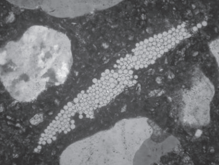
section petro-micrograph, horizontal field of view
730 microns.)
Figure 6 shows the cross-section of a single reinforcing strand in typical multifilament glass–FRC at 28 days. The cement matrix is in close contact with most (but not all) of the perimeter filaments but does not penetrate into the centre of the strand.
As the composite ages and the cement matrix continues to hydrate, contact between the perimeter fibres and the matrix will become more intimate, and hydration products will gradually begin to be deposited between the filaments, changing the bond with time.
Bonding
Three types of bond are available in FRC:
- elastic bonding – the fibres adhere to the matrix
- frictional bonding – friction between the fibres and the matrix provides resistance to pullout
- mechanical bonding – the fibres are purposely deformed along their length such that they are mechanically interlocked with the matrix. This can be thought of as ‘enhanced’ frictional bond.
Frictional bonding dominates the important part of FRC stress–strain behaviour – the post cracking region and so is of most interest. Pull-out tests are used to estimate frictional bond. These are difficult to interpret, and reported results vary widely, but typical values for the average bond stress (t) in monofilament FRC with smooth cylindrical fibres are around 0.1, 0.5 and 1 MPa for polyethylene, polypropylene and steel fibres, respectively.
Crimping the fibres to provide mechanical bonding can effectively increase this value by a factor of around 4 (Bentur and Mindess, 2007, p. 62). Evaluating pull-out tests for multifilament fibres is even more difficult, not least because the contact perimeter between the fibre bundle and the matrix is not known.
Typical reported values of τ are around 0.6 MPa for carbon, and 0.5–1 MPa for fresh and aged glass– FRC, respectively (Bentur and Mindess, 2007; Purnel et al., 2000). Adding microsilica, ggbs or other additions will affect the interfacial properties and increase the bond strength, as they densify the matrix.