Upgrading of metallic structural members
Advanced polymer composite materials have not been utilised to upgrade metallic structures to the same extent as they have been for reinforced concrete structures.
However, as a result of research into this subject, which commenced at the latter part of the 20th century (Mertz and Gillespie, 1996; Mosallam and Chakrabarti, 1997; Luke, 2001; Moy, 2001; Tavakkolizadeh and Saadatmanesh, 2003; Cadei et al., 2004; Moy, 2004; Luke and Canning, 2004, 2005; Photiou et al., 2006; Hollaway et al., 2006; Zhang et al., 2006), there have been a number of applications of CFRP to metallic structures that have shown that the technique can have significant benefits over alternative methods of strengthening.
The number of applications to date in the UK has led to the publication of two comprehensive guidance documents:
- ICE Design & Practice Guide. FRP Composites – Life Extension and Strengthening of Metallic Structures (Moy, 2001).
- CIRIA Report C595. Strengthening Metallic Structures using Externally-Bonded FRP (Cadei et al., 2004).
Design guidance has also been published recently by the Italian National Research Council (CNR, 2006), Schnerch et al. (2006) and ISIS (Canada), 2007. FRP strengthening can be used to address any of the structural deficiencies described in the concrete section.
The reasons for using FRP to rehabilitate a metallic or concrete structure may be similar; however, the way in which the FRP works with an existing metallic structure can often be very different to that in a concrete structure. The FRP composite plate material used for the bonding operation is either the ultra-high-modulus (European definition) or the high-modulus (European definition) CFRP, AFRP (Kevlar 49) or possibly GFRP composites and these will be fabricated by one of four methods:
- The pultrusion technique, in which the factory made rigid pre-cast FRP plate is bonded onto the degraded member with cold-cure adhesive.
- The factory made rigid fully cured FRP prepreg plate bonded to the degraded member with coldcure adhesive.
- The low-temperature mould prepreg FRP prepreg/ adhesive film placed onto the structural member and both components compacted and cured under vacuum at an elevated temperature.
- Vacuum infusion (The Resin Infusion under Flexible Tooling (RIFT) process).
It should be mentioned that the ultra high-modulus carbon fibre composite has a low strain to failure, of the order of 0.4% strain, and a modulus of elasticity of the composite of about 40 GPa, so the system will fail with a small inelastic characteristic.
The high-modulus CFRP composites have a value of ultimate strain of the order of 1.6% strain for modulus of elasticity of 28 GPa. This implies that the material is ductile and is unlikely to fail in a rehabilitation situation by ultimate strain but by some other method (Photiou, 2006).
Internal reinforcement to concrete members
FRP rebars for reinforcing concrete members are generally fabricated by the pultrusion method (Nanni, 1993; ACI, 1996; Pilakoutas, 2000; Bank, 2006). The rebars can be manufactured from carbon, aramid and glass fibres using epoxy or vinylester polymers.
The surfaces of pultruded composites are smooth and therefore it is necessary to post-treat them to develop a satisfactory bond characteristic between the concrete and the rebar. Several techniques are used for this, including:
- applying a peel-ply to the surface of the pultruded bar during the manufacturing process; the peel ply is removed before encasing the bar with concrete, thus leaving a rough surface on the pultruded rebar
- over-winding the pultruded rebar with additional fibres
- bonding a layer of sand with epoxy adhesive to the surface of the pultruded rod; this is a secondary operation at the end of the pultrusion line.
The features and benefits of using FRP rebars are:
- they are non-corrosive – they will not corrode when exposed to a wide variety of corrosive elements, including chloride ions, and are not susceptible to carbonation-initiated corrosion in a concrete environment
- they are non-conductive – they provide good electrical and thermal insulation
- they are fatigue resistant – they perform well in cyclic loading situations
- they are impact resistant – they resist sudden and severe point loading
- they have magnetic transparency – they are not affected by electro-magnetic fields.
FRP rebars manufactured from a thermosetting resin (viz. vinlyesters or epoxies) are unable to be reshaped once they are polymerised and therefore cannot be bent on site. If bends are required, for instance anchorages or stirrups, they must be produced by the FRP rebar manufacturer as a special item, but their strength at the bend will be considerably reduced.
One option would be to use thermoplastic polymers as spliced bends; this material can be bent on site but the system is still in its development stage. Although carbon and aramid fibre composites are higher in cost than are glass composites, they are inert to alkaline environment degradation and can be used in the most extreme cases.
FRP confining of concrete columns
The confinement of concrete enhances its durability and strength. In the past it was usual to enhance reinforced concrete columns by the addition of longitudinal steel bars and concrete around existing columns. A further method consisted of placing a steel jacket around a column. However, these two methods are difficult to apply.
Numerous experiments since the 1980s have demonstrated the effectiveness of FRP composites for confining RC columns by external wrapping with composite sheets (De Lorenzis and Tepfers, 2003).
Confinement with polymer composite strands or sheets of composite prepreg have shown many advantages in compression over the above confinement methods. These include:
- high specific strength and stiffness
- relative ease of applying the composite materials in construction site situations
- with the large ratio of the areas of the circumferential to axial fibres, the modulus of elasticity of the FRP axial composite is small, thus allowing the concrete to take essentially the entire axial load
- the tensile strength in the circumferential direction is very large and essentially independent of the value of the axial stress
- ease and speed of application result from the FRP’s low weight
- their minimal thickness does not alter the shape and size of the strengthened elements
- the good corrosion behaviour of FRP materials makes them suitable for use in coastal and marine structures.
Composite wrapping systems have been used throughout the world on a number of bridges, mainly for seismic loading, predominately in Japan and the USA. The available composite systems include epoxy with glass fibre, aramid fibre or carbon fibre fabric materials.
Both wet lay-up and prefabricated systems are normally used with the principal fibre direction perpendicular to the axis of the member. The wrapping can be applied either continuously over the surface (which poses the problem of moisture migration) or as strips with a particular width between them (the spaced confining devices provide reduced effectiveness compared to the equal continuous device, as portions of the column between adjacent strips remain unconfined).
The FRP confinement action is passive, that is, it arises as a result of the lateral expansion of the concrete core under axial load, and the confining reinforcement develops a tensile stress balanced by pressures reacting against the concrete’s lateral expansion.
An FRP confined column can deform longitudinally much more under an extreme stress state than a conventional material system before failure. The lateral confinement of the concrete provides an order of magnitude improvement in the ultimate compressive strain.
Confinement is most effective for circular columns, as the confinement pressure is in this case uniform. Both strength and ductility can be significantly enhanced. In the case of rectangular columns, the confining action is less efficient. The achievable increase in strength is usually modest or negligible, but a ductility enhancement can still be obtained. The effectiveness decreases as the cross-sectional aspect ratio increases. The REPLARK and the XXsys are the two main systems available for site work.
FRP/concrete duplex beam construction
The combination of a fibre matrix composite and a conventional civil engineering material, i.e. concrete, to form a ‘duplex’ beam was researched by Triantafillou and Meier (1992). Figure 9a shows the basic ‘duplex’ beam that they conceived.
The emphasis of their work was to use the concrete in the compressive and APCs in the tensile regions of a beam. Thus the two materials are used to their best structural advantage.
Hulatt et al. (2003a, 2003b, 2004) further developed the idea by testing and numerically analysing a Tee system under various geometries and loading configurations.
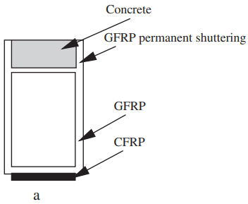
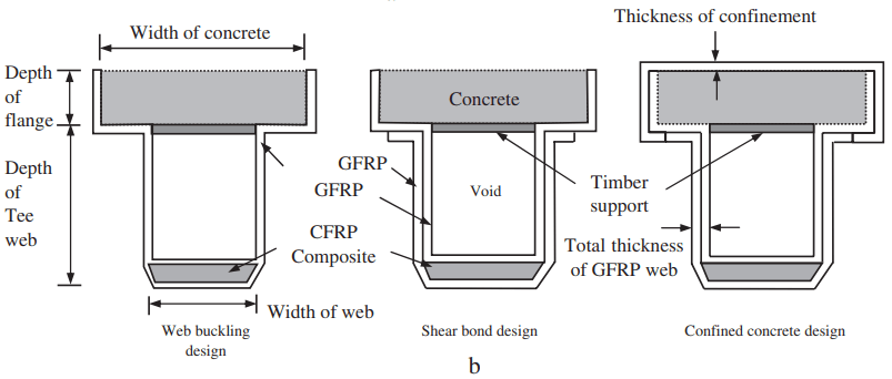
Figure 9b shows diagrammatic elevations of FRP/concrete beams; the items shown are a design for web buckling; a design for shear bond; and a design for confining the concrete (which aids the compression strength of the concrete).
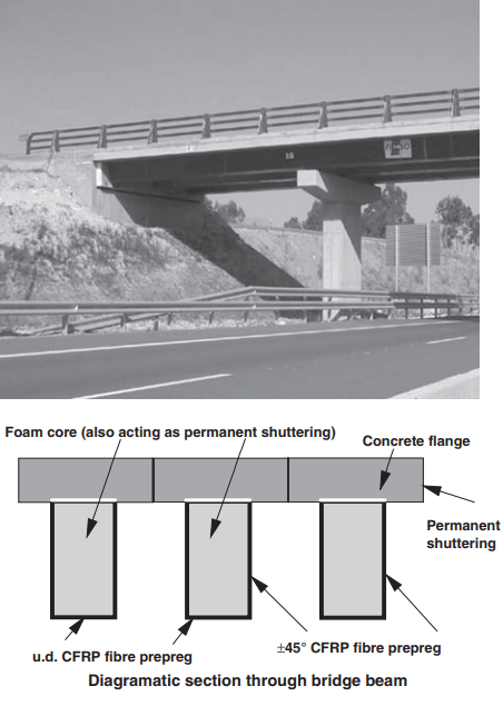
The FRP composite materials used in this work were prepregs of glass and carbon supplied by Advanced Composites Group (ACG), Heanor, UK. As a result of the above work NECSO Entrecanales Cubiertas, Madrid, Spain and ACG have developed an equivalent beam; an element consisting of this beam and the completed bridge are shown in Fig. 10.
NECSO Entrecanales Cubiertas, Madrid, Spain and ACG
Ltd. Heanor, UK
This utilises the high compressive strength of concrete and the high tensile strength of the carbon fibre. Load testing at 80% of ultimate load demonstrated that the beam behaved as a typical steel girder, indicating that the traditional principles of flexural design can be utilised. Analysis indicated that the manufacturing cost of a duplex beam is comparable to that of long-span concrete beams.
The real benefit is in the significant cost savings provided owing to the lower weight and reduction of life cost of the beam. Obvious opportunities for this technology are more site installations and refurbishment of infrastructure in developing countries or war-damaged regions.
Polymer bridge bearings and vibration absorbers
Bridge bearings
Bridge bearings are used to transfer loads from the deck of a bridge to its sub-structure and thence to its foundation and to avoid damage from:
- vehicle movements on bridges
- thermal expansion of bridges
- loading to piers, thus reducing reaction forces and rotational movement to within safe limits.
There are broadly two types of bridge bearing, elastic materials and roller bearings. In elastomeric materials, the bearing is made from one of the following polymers:
- neoprene polymer
- natural rubber
- styrene butadiene rubber (SBR).
The bearings are either plain pad-and-strip bearings or laminates with steel plates. Movements are accommodated by the basic mechanisms of internal deformation.
The bearings allow the deck to be flexible in shear to accommodate deck translation and rotation but they are stiff in compression to accommodate vertical loads. The stability of the bearings must be taken into account in the design and they must be able to absorb and isolate energy from impacts and vibrations.
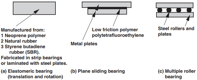
Figure 11a illustrates a typical bearing. A diagrammatic sketch of a plane sliding bearing is shown in Fig. 11b; the material used with this system is the low-friction polymer polytetrafluoroethylene (PTFE), which slides against a metal plate.
This bearing resists loads in the vertical direction but not rotational movements in the longitudinal or transverse directions; the rotational and transverse loads are resisted by providing mechanical keys.
A typical multi-roller bearing is shown in Fig. 11c. Vertical loads only can generally be resisted by these bearings, but large longitudinal movements can be accommodated. The roller material tends to be steel.
Seismic isolation systems
Seismic isolation systems have two functions:
- to introduce flexibility at the base of a building structure in the horizontal plane
- to provide damping elements to restrict the amplitude of the motion caused by the earthquake.
There are three basic elements in a system, which have to provide:
- a damper or energy dissipator to control relative deflections between a building and the ground. Elastomers with high damping characteristics could be used for this element
- a flexible mounting so that the period of vibration of the total system is lengthened sufficiently to reduce the force response
- rigidity under low service load levels (e.g. wind or minor earthquakes).
The rubber-based isolation system is manufactured from:
- a high damping steel–rubber member
- a lead–rubber laminations member of thickness between 160 mm and 200 mm.
The typical residential buildings of reinforced concrete frame or wall construction of more than five stories high use the lead–rubber type. Other systems use elastomeric pads constructed of neoprene layers in series and are available with alternating raised diagonal ribs or square-cell pattern.
Anti-vibration and structural isolation systems
In areas of ground-borne vibrations due to low frequency rumble from underground and surface trains there is a risk of sound transmission from the rolling stock. Building structures might require isolation systems to be installed in their foundations.
In these cases the isolation of the structure can be effected by placing elastomeric bearings (such as polyurethane-bound rubber granulate, polyurethane mixed-cell structure foam, a medium-density closed cell structural foam such as isolation sheets, etc.) under the foundations of the building. The isolators are installed on top of the basement walls or columns. Applications of this technology include:
- foundation isolation
- column heads
- pile cap
- perimeter isolation
- floating floor systems.
Use of geosynthetics
The use of geosynthetics in civil engineering is a wide subject and cannot be competently covered here. However, some of the uses of this family of materials are in the form of:
- Geotextiles to prevent intermixing of the soft subgrade with granular material during the passage of lorries on civil engineering construction sites.
- Geotextile overlay to prevent existing cracks in pavements migrating into new overlay surfaces during the maintenance of asphalt roads.
- Geolinear elements used as anchors to stabilise an RC retaining wall.
- Geogrids acting as reinforced earth to reinforce slopes and retaining walls.
- Geomembranes to prevent loss of liquid from containment structures, such as water courses.
- Geocomposites, which have a wide range of applications, e.g. prefabricated drains, flexible skins, etc.